


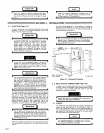
SECTION
5-FUNCTION
OF
GENERATOR
CONTROLS
The
contacts
of
the
FINE
AMPERAGE
control
are
of
the
continuous
contact
type,
thereby
making
it
possible
to
fine
adjust
the
amperage
output
while
i
welding
The
scale
surrounding
the
FINE
AMPERAGE
control
is
calibrated
from
0
to
100
percent
in
increments
of
ten.
Due
to
this
percentage
calibration,
it
should
be
noted
that
if
the
operator
is
using
this
scale
to
select
a
fine
amperage
setting,
the
operator
is
selecting
a
percentage
of
the
coarse
range
in
use
and
not
an
actual
amperage
value.
I
The
FINE
AMPERAGE
control
must
be
rotated
to
the
100
(full
counterclockwise)
position
whenever
the
120/240
volts
power
plant
is
being
utilized.
The
FINE
AMPERAGE
control
may
be
in
any
position
when
using
the
120
VOLTS
AC
duplex
receptacle
on
the
front
panel.
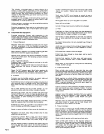
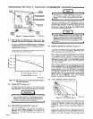
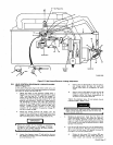
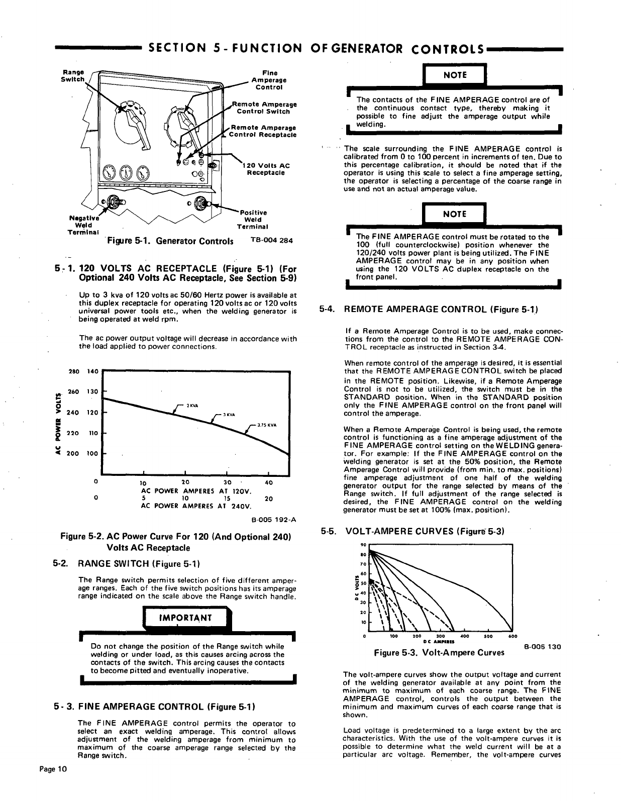
Fi~jre
5-1.
Generator
Controls
TB-004
284
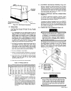
5.
1.
120
VOLTS
AC
RECEPTACLE
(Figure
5-1)
(For
Optional
240
Volts
AC
Receptacle,
See
Section
5-9)
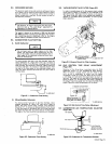
Up
to
3
kva
of
120
volts
ac
50/60
Hertz
power
is
available
at
this
duplex
receptacle
for
operating
120
volts
ac or
120
volts
universal
power
tools
etc.,
when
the
welding
generator
is
being
operated
at
weld
rpm.
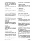
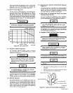
The
ac
power
output
voltage
will
decrease
in
accordance
with
the
load
applied
to
power
connections.
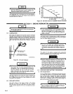
280
140
I
U
260
130
>
240
120
220
110
~
200
100
0
0
20
30
40
AC
POWER
AMPERES
AT
120V.
5
10
15
20
AC
POWER
AMPERES
AT
240V.
B-005
192-A
Figure
5-2.
AC
Power
Curve
For
120
(And
Optional
240)
Volts
AC
Receptacle
5-2.
RANGE
SWITCH
(Figure
5-1)
The
Range
switch
permits
selection
of
five
different
amper
age
ranges.
Each
of
the
five
switch
positions
has
its
amperage
range
indicated
on
the
scale
above
the
Range
switch
handle.
5-4.
REMOTE
AMPERAGE
CONTROL
(Figure
5-1)
If
a
Remote
Amperage
Control
is
to
be
used,
make
connec
tions
from
the
control
to
the
REMOTE
AMPERAGE
CON
TROL
receptacle
as
instructed
in
Section
3-4.
When
remote
control
of
the
amperage
is
desired,
it
is
essential
that
the
REMOTE
AMPERAGE
CONTROL
switch
be
placed
in
the
REMOTE
position.
Likewise,
if
a
Remote
Amperage
Control
is
not
to
be
utilized,
the
switch
must
be
in
the
STANDARD
position.
When
in
the
STANDARD
position
only
the
FINE
AMPERAGE
control
on
the
front
panel
will
control
the
amperage.
When
a
Remote
Amperage
Control
is
being
used,
the
remote
control
is
functioning
as
a
fine
amperage
adjustment
of
the
FINE
AMPERAGE
control
setting
on
the
WELDING
genera
tor.
For
example:
If
the
FINE
AMPERAGE
control
on
the
welding
generator
is
set
at
the
50%
position,
the
Remote
Amperage
Control
will
provide
(from
mm.
to
max.
positions)
fine
amperage
adjustment
of
one
half
of
the
welding
generator
output
for
the
range
selected
by
means
of
the
Range
switch.
If
full
adjustment
of
the
range
selected
is
desired,
the
FINE
AMPERAGE
control
on
the
welding
generator
must
be
set
at
100%
(max.
position).
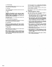
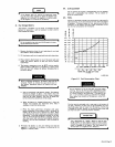
5-5.
VOLT-AMPERE
CURVES
(Figur~5-3)
0
100
200 300
400
300 600
DC
AMPIIIS
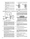
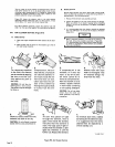
Figure
5-3.
Volt-Ampere
Curves
B-005
130
The
volt-ampere
curves
show
the
output
voltage
and
current
of
the
welding
generator
available
at
any
point
from
the
minimum
to
maximum
of
each
coarse
range.
The
FINE
AMPERAGE
control,
controls
the
output
between
the
minimum
and
maximum
curves
of
each
coarse
range
that
is
shown.
Load
voltage
is
predetermined
to
a
large
extent
by
the
arc
characteristics.
With
the
use
of
the
volt-ampere
curves
it
is
possible
to
determine
what
the
weld
current
will
be
at
a
particular
arc
voltage.
Remember,
the
volt-ampere
curves
tMPORTANT
I
U
Do
not
change
the
position
of
the
Range
switch
while
welding
or
under
load,
as
this
causes
arcing
across
the
contacts
of
the
switch.
This
arcing
causes
the
contacts
to
become
pitted
and
eventually
inoperative.
U
I
5-
3.
FINE
AMPERAGE
CONTROL
(Figure
5-1)
The
FINE
AMPERAGE
control
permits
the
operator
to
select
an
exact
welding
amperage.
This
control
allows
adjustment
of
the
welding
amperage
from
minimum
to
maximum
of the
coarse
amperage
range
selected
by
the
Range
switch.
Page
10