


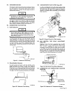


tMPORTANT
Replace
the
spark
arrestor
if
inspection
reveals
any
signs
of
failure.
I
The
engine
exhaust
system
on
this
welding
generator
has
not
been
equipped
with
a
spark
arrestor
unless
it
was
specifically
ordered
as
an
optional
accessory.
A
spark
arrestor,
maintained
in
effective
working
order,
is
mandatory
if
this
welding
generator
is
to
be
operated
in
a
National
Forest,
or
on
California
grasslands,
brush,
or
forest
covered
land
(see
Section
4442
of
California
Public
Resources
Code).
For
other
areas,
check
your
state
and
local
laws.
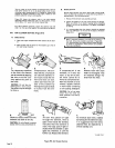
A.
Inspection
1.
Visually
examine
the
outside
of
the
device
for
holes,
cracks,
or
metal
corrosion.
2.
With
the
engine
stopped,
look
inside
the
spark
arrestor
outlet
tube with
a
flashlight
or
other
light
source.
Visually
examine
the
vanes
and
the
outlet
tube
for
metal
or
weld
failure.
The
vanes
must
be
firmly
attached
to
the
inlet
tube
and
the
outlet
tube
must
be
completely
intact
(this
is
an
important
factor
in
maintaining
spark
arresting
efficiency).
3.
Check
the
mounting
clamp
to
ensure
that
the
spark
arrestor
is
securely
mounted.
1.
Stop
the
engine
and
allow
the
exhaust
system
to
cool.
2.
Remove
the
cleanout
plug
from
the
bottom
of
the
spark
arrestor
with
a
wrench.
If
a
crust
has
formed
over
the
hole,
break
it
loose
with
a
screwdriver
or
similar
tool.
3.
Start
the
engine
and
run
it
at
idle
rpm
to
blow
collected
particles
out
the
cleanout
hole.
If
particles
are
slow
to
discharge,
momentarily
cover
the
end
of
the
exhaust
stack.
4.
Stop
the
engine.
Replace
and
secure
the
cleanout
plug.
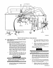
TC-003
226
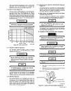
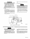
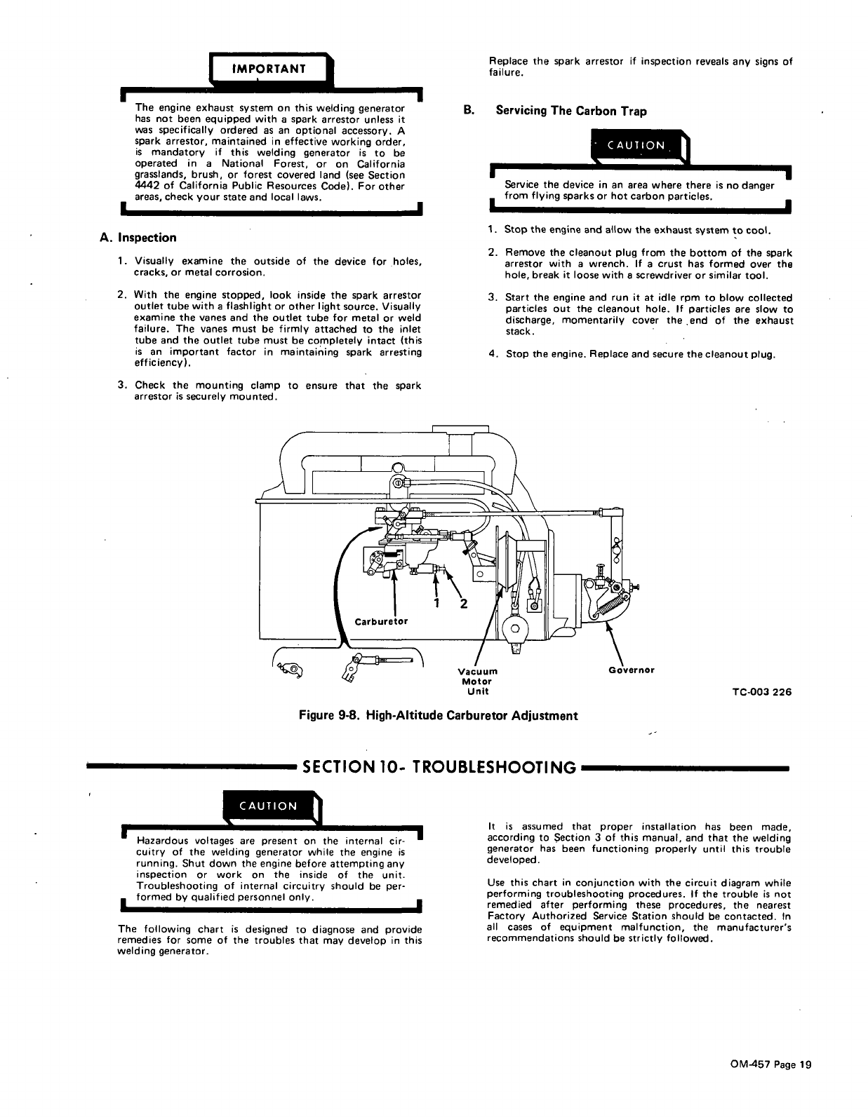
Figure
9-8.
High-Altitude
Carburetor
Adjustment
SECTION
10-
TROUBLESHOOTING
CAUTION
Hazardous
voltages
are
present
on
t~ternalcir
cuitry
of
the
welding
generator
while
the
engine
is
running.
Shut
down
the
engine
before
attempting
any
inspection
or
work
on
the
inside
of
the
unit.
Troubleshooting
of
internal
circuitry
should
be
per
formed
by
qualified
personnel
only.
It
is
assumed
that
proper
installation
has
been
made,
according
to
Section
3
of
this
manual,
and
that
the
welding
generator
has
been
functioning
properly
until
this
trouble
developed.
Use
this
chart
in
conjunction
with
the
circuit
diagram
while
performing
troubleshooting
procedures.
If
the
trouble
is
not
remedied
after
performing
these
procedures,
the
nearest
Factory
Authorized
Service
Station
should
be contacted.
In
all
cases
of
equipment
malfunction,
the
manufacturers
recommendations
should
be
strictly
followed.
I
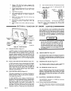
B.
Servicing
The
Carbon
Trap
I
I
I
I
Service
the
device
in
an
area
where
there
is
no
danger
from
flying
sparks
or
hot
carbon
particles.
Vacuum
Motor
Unit
The
following
chart
is
designed
to
diagnose
and
provide
remedies
for
some
of
the
troubles
that
may
develop
in
this
welding
generator.
OM-457
Page
ig