


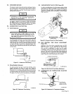


rotation
of
the
Screw
(10)
will
decrease
engine
rpm.
B.
Rotate
the
idle
mixture
adjustment
Screw
(11)
clockwise
until
the
engine
begins
to
falter
or
roll,
then
rotate
the
screw
(11)
counterclock
wise
until
the
engine
operates
Smoothly.
Rotating
the
screw
(11)
clockwise
restricts
the
air
flow,
making
the
air-fuel
mixture
richer.
Rotating
the
screw
(11)
counterclockwise
ad
mits
more
air,
making
the
air-fuel
mixture
leaner.
6.
Connect
the
vacuum
motor
linkage
(12)
from
the
vacuum
motor
unit
to
the
carburetor.
7.
Manually
pivot
the
vacuum
motor
arm
(14)
until
screw
(16)
butts
against
the
vacuum
motor
unit
mounting
plate.
If
this
is
not
possible
due
to
the
idle
screw
(10)
butting
against
the
stop
(3)
before
the
screw
(16)
butting
against
the
mounting
plate,
adjust
Screw
(16)
so
that
screw
(16)
butts
against
the
vacuum
motor
uni~
mounting
plate
before
idle
screw
(10)
butts
against
stop
(3).
IMPORTANT
Ensure
that
the
screw
(16)
butts
against
the
mounting
plate
before
the
idle
screw
(10)
butts
against
the
stop
(3)
prior
to
placing
the
IDLE
CONTROL
switch
in
the
AUTOMATIC
IDLE
position.
8.
Place
the
IDLE
CONTROL
s~it~h
in
the
AUTO
MATIC
IDLE
position.
Operation
of
the
idling
device
is
automatic
when
the
IDLE
CONTROL
switch
is
in
the
AUTOMATIC
IDLE
position.
Once
the
engine
is
started,
engine
rpm
will
remain
at
idle
until
an
arc
is
established,
at
which
time
the
engine
immediately
comes
up
to
weld
rpm.
When
the
arc
is
broken,
a
time
delay
will
exist
before
the
engine
begins
to
return,
to
idle
rpm.
The
length
of
this
time
delay
is
controlled
by
the
setting
of
the
time-delay
screw
A
in
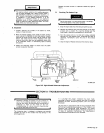
Figure
9-4.
If
the
engine
does
not
go
to
idle
rpm
after
about
ten
seconds,
adjust
the
time-delay
screw
(A)
for
the
desired
time
delay.
This
screw
is
located
on
the
vacuum
line
fitting
going
into
the
intake
manifold
of
the
engine.
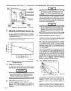
Figure
9-4
shows
the
adjustment
of
this
screw.
9.
When
the
engine
has
gone
to
Idle
rpm,
adjust
screw
(16)
until
1050
rpm
is
obtained.
NOTE
-
Do
not
readjust
the
idle
rpm
screw
(10)
when
adjust~
ing
the
vacuum
motor
idle
rpm.
I.
Check
the
linkage
(12)
for
freedom
of
movement
throughout
its
entire
travel;
If
the
linkage
(12)
is
bind
ing
due
to
the
linkage
socket
(14)
)eing
cocked
rela
tive
to
the
linkage
(12)
fixed
end
adjust
the
length
of
the
linkage
and
repeat
Steps
7.
8,
&
9.
A.
IF
REGULATION
RANGE
IS
TOO
BROAD
Decrease
the
governor
spring
(22)
tension
by
sliding
the
sensitivity
adjustment
screw
(23)
inward.
B.
IF
REGULATION
RANGE
IS
TOO
NARROW
Increase
the
governor
spring
(22)
tension
by
sliding
the
sensitivity
adjustment
screw
(23)
outward.
C.
IF
ENGINE
SURGES
(HUNTS)
UNDER
LOAD
Increase
the
governor
spring
(22)
ten
sion
by
sliding
the
sensitivity
adjustment
screw
(23)
outward.
12.
Tighten
the
two
locking
nuts
(21)
to
maintain
the
desired
governor
sensitivity.
Readjust
the
governor
sensitivity
by
repeating
Step
11.
NOTE
Whenever
the
governor
sensitivity
(Step
11)
is
adjust
ed,
the
governor
speed
(Step
10)
must
be
readjusted.
Whenever
the
governor
speed
(Step
10)
is
adjusted,
the
governor
sensitivity
(Step
11)
may
need
readjustment.
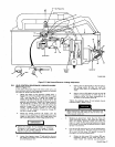
9-10.
HIGH
ALTITUDE
CARBURETOR
MODIFICATION
(Optional)
(Figure
9-8)
The
Zenith
carburetor
may
be
equipped
with
an
adjustable
main
jet
for
high
altitude
operation
(above
4000
ft).
Minor
adjustment
will
be
necessary
for
proper
operation
at
a
particular
altitude.
Whenever
a
carburetor
adjustment
is
deemed
necessary,
refer
to
figure
9-8
and
proceed
as
follows:
Loosen
the
main
adjustment
screw
locking
nut
(1).
Apply
a
near
full
engine
load
to
the
welding
generator.
Rotate
the
main
adjustment
screw
(2)
clockwise
until
the
engine
begins
to
falter
and
lose
rpm.
Rotate
the
main
adjustment
screw
(2)
counterclockwise
until
the
engine
operates
smoothly,
then
continue
counterclockwise
rotation
for
1/4
turn.
Ro
tating
the
screw
(2)
clockwise
restricts
the
fuel
flow,
making
the
air-fuel
mixture
leaner.
Rotating
the
screw
(2)
counter
clockwise
admits
more
fuel,
making
the
air-fuel
mixture
richer.
Remove
the
engine
load.
Tighten
the
locking
nut
(1).
~icting
the
fuel
point
where
the
mix
tUre
is
too
lean
will
cause
valve
burning.
9-11.
KEY
TYPE
IGNITION
SWITCH
LUBRICATION
(If
Applicable)
Periodically,
depending
on
the
location
of
the
unit
and
the
amount
of
moisture
in
the
air,
or
when
binding
is
noticed,
remove
the
key
and
lubricate
the
Ignition
switch
by
spraying
a
generous
amount
of
lubricant
into
the
key
slot.
Wipe
excess
of
f
of
the
nameplate.
It
is
recommended
that
lubriplate
chain
and
cablefluid
which
is
non-gumming
and
is
also
an
anti-oxidant
and
penetrating
oil
or
a
similar
product
be
u~ed.
10.
Place
the
IDLE
CONTROL
switch
in
the
LOCK
OUT
position.
Loosen
the
governor
speed
adjusting
screw
securing
nut
(19).
Adjust
the
governor
speed
adjust
ment
screw
(20)
until
a
high
idle
rpm
of
1800
is
ob
tained.
Tighten
the
securing
nut
(19)
to
maintain
the
governor
speed
setting.
11.
Check
the
governor
engine
regulation
by
applying
and
removing
the
engine
load.
If
a
governor
sensitivity
adjustment
is
deemed
necessary,
loosen
one
of
the
two
locking
nuts
(21)
and
proceed
with
the
following
instructions:
Internal
combustion
engines
operating
in
a
highly
com
bustible
environment
are
a
common
fire
hazard.
Glowing
carbon
particles
blown
out
with
the
exhaust
can
retain
sufficient
heat
to
ignite
materials.
While
no
practical
spark
arresting
device
will
stop
all
sparks,
this
device
will
minimize
fire
hazards
by
removing
and
trapping
most
solid
particles
provided
that
it
is
properly
maintained.
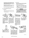
The
carbon
trap
should
be
serviced
weekly
or
every
50
operating
hours,
whichever
occurs
first.
The
entire
spark
arrestor
should
be
inspected
every
1000
operating
hours
or
three
times
per
season:
U
I
9-12.
SPARK
ARRESTOR
(Optional)
Page
18