


PARAMETERS
87
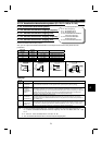
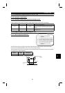
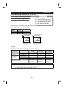
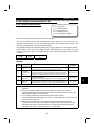
When 100 is set in Pr. 52, the monitored values during stop and during operation differ as indicated below:
(The LED on the left of Hz flickers during a stop and is lit during running.)
Pr. 52
0 100
During
operation/during stop
During stop During operation
Output frequency Output frequency Set frequency
Output frequency
Output current Output current
Output voltage Output voltage
Alarm display Alarm display
Note: 1. During an error, the output frequency at error occurrence is displayed.
2. During MRS, the values are the same as during a stop.
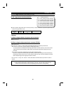
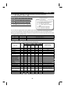
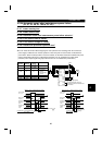
Note: 1. The monitoring of items marked
×
cannot be selected.
2. By setting "0" in Pr. 52, the monitoring of "output frequency to alarm display" can be selected in
sequence by the
SET
key.
3. *"Frequency setting to output terminal status" on the PU main monitor are selected by "other
monitor selection" of the parameter unit (FR-PU04).
4. **The load meter is displayed in %, with the current set in Pr. 56 regarded as 100%.
5. The actual operation time displayed by setting "23" in Pr. 52 is calculated using the inverter
operation time. (Inverter stop time is not included.) Set "0" in Pr. 171 to clear it.
6. When Pr. 53 = "0", the level meter display of the parameter unit can be erased.
7. By setting "1, 2, 5, 6, 11 or 17" in Pr. 53, the full-scale value can be set in Pr. 55 or Pr. 56.
8. The cumulative operation time and actual operation time are calculated from 0 to 65535 hours,
then cleared, and recalculated from 0.
When the operation panel (FR-DU04) is used, the display shows "----" after 9999 or more hours
have elapsed.
Whether 9999 or more hours have elapsed or not can be confirmed on the parameter unit
(FR-PU04).
9. The actual operation time is not calculated unless the inverter has operated for longer than one
hour continuously.
10.When the operation panel (FR-DU04) is used, the display unit is Hz, V or A only.
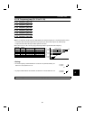
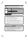
REMARKS
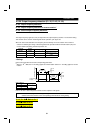
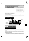
For the monitor set in Pr. 52, its display position depends on the set value.
Factory setting
SET SET
SET
FR-DU04
CONTROL PANEL
Hz
MON EXT PU
A
V
REV FWD
FR-DU04
CONTROL PANEL
Hz
MON EXT PU
A
V
REV FWD
FR-DU04
CONTROL PANEL
Hz
MON EXT PU
A
V
REV FWD
FR-DU04
CONTROL PANEL
Hz
MON EXT PU
A
V
REV FWD
SET
Output frequency monitor
Output current monitor
With alarm
Output voltage monitor
First monitor (It is shown at power-on)
Second monitor
Third monitor
Alarm monitor
1)
2)
1)
1)
3)
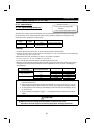
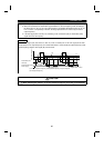
1) For the set value "5 to 14" (displayed at the third monitor position)
Output frequency monitor
First monitor
SET
Second monitor
Output current monitor
Third monitor
Set value "5 to 14" monitor
SET
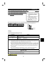
2) For the set value "17, 24" (displayed instead of output current monitor)
Output frequency monitor
First monitor
SET
Second monitor
monitor
Set value "17, 24"
Third monitor
Output current monitor
SET
3) For the set value "20, 23, 25" (displayed instead of output voltage monitor)
Output frequency monitor
First monitor
SET
Second monitor
Output current monitor
Third monitor
Set value "20, 23, 25"
monitor
SET
4