PARAMETERS
86
4.2.22 Monitor display / FM, AM terminal function selection
(Pr. 52 to Pr. 54, Pr. 158)
Pr. 52 "DU/PU main display data selection"
Pr. 53 "PU level display data selection"
Pr. 54 "FM terminal function selection"
Pr. 158 "AM terminal function selection"
You can select the signals shown on the operation panel (FR-DU04)/parameter unit (FR-PU04) main display
screen and on the parameter unit (FR-PU04) level meter and signals output to the FM and AM terminals.
#
There are two different signal outputs: FM pulse train output terminal and AM analog output terminal. Select
the signals using Pr. 54 and Pr. 158.
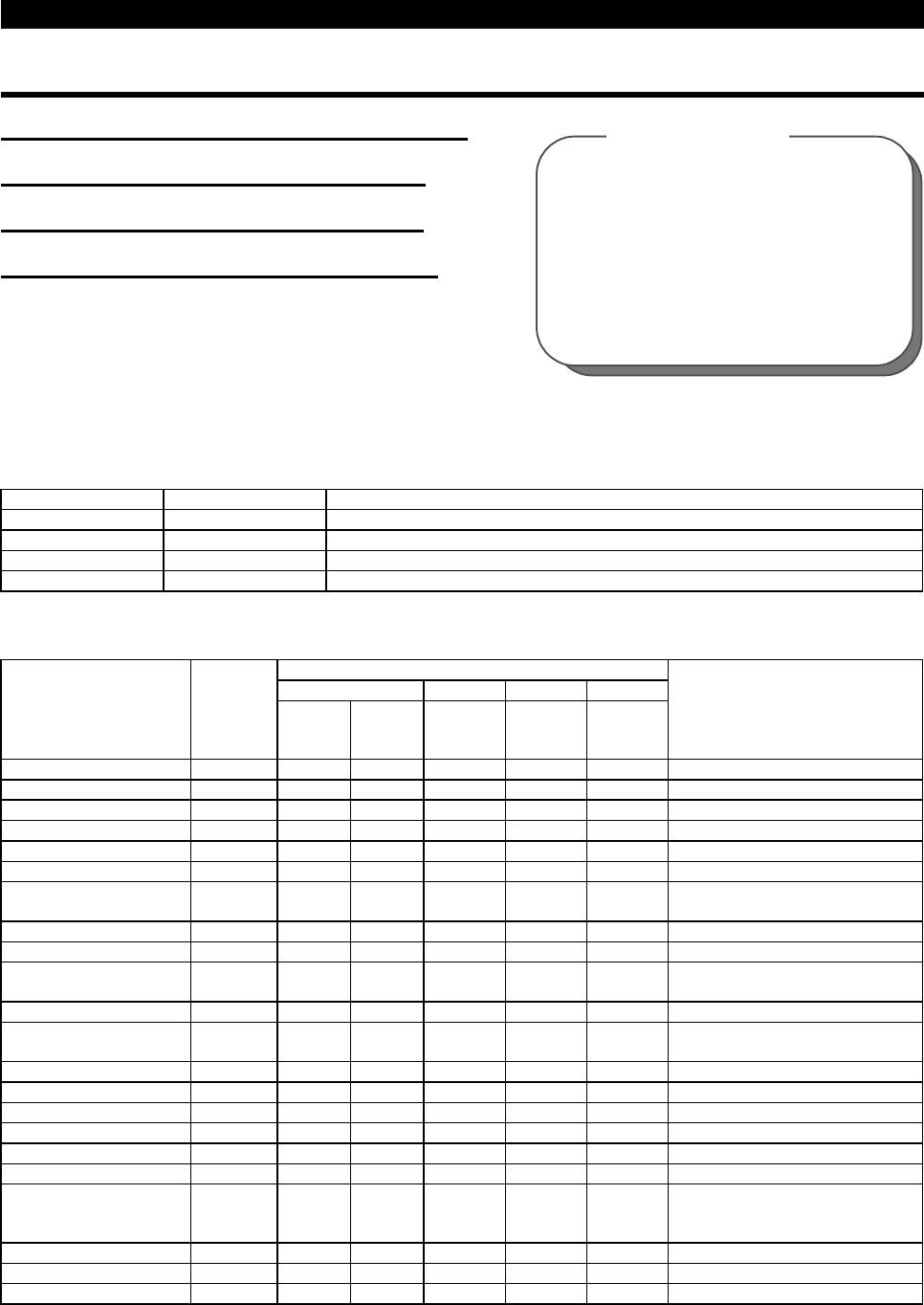
Parameter Number Factory Setting Setting Range
52 0 0, 5, 6, 8, 10 to 14, 17, 20, 23, 24, 25, 100
53 1 0 to 3, 5, 6, 8, 10 to 14, 17
54 1 1 to 3, 5, 6, 8, 10 to 14, 17, 21
158 1 1 to 3, 5, 6, 8, 10 to 14, 17, 21
<Setting>
Set Pr. 52 to Pr. 54 and Pr. 158 in accordance with the following table:
Parameter Setting
Pr.52 Pr.53 Pr.54 Pr.158
Signal Type
Display
Unit
DU
LED
PU
main
monitor
PU level
meter
FM
terminal
AM
terminal
Full-Scale Value of
FM, AM, Level Meter
No display
× ×
0
××
Output frequency Hz 0/100 0/100 1 1 1 Pr. 55
Output current A 0/100 0/100 2 2 2 Pr. 56
Output voltage V 0/100 0/100 3 3 3 400V or 800V
Alarm display
0/100 0/100
×××
Frequency setting Hz 5 * 5 5 5 Pr. 55
Running speed r/min 6 * 6 6 6
Pr. 55 value converted into Pr. 37
value
Converter output voltage V 8 * 8 8 8 400V or 800V
Regenerative brake duty %
×
*
×××
Electronic overcurrent
protection load factor
% 10 * 10 10 10 Protection operation level
Output current peak value A 11 * 11 11 11 Pr. 56
Converter output voltage
peak value
V 12 * 12 12 12 400V or 800V
Input power kW 13 * 13 13 13 Rated power of inverter rating
×
2
Output power kW 14 * 14 14 14 Rated power of inverter rating
×
2
Input terminal status
×
*
×××
Output terminal status
×
*
×××
Load meter ** % 17 17 17 17 17 Pr. 56
Cumulative operation time h 20 20
×××
Reference voltage output
× × ×
21 21
1440Hz is output to FM terminal.
Full-scale voltage is output to AM
terminal.
Actual operation time h 23 23
×××
Motor load factor % 24 24
×××
Rated inverter current
×
2
Cumulative power kW 25 25
×××
Pr. 37 "speed display"
Pr. 55 "frequency monitoring reference"
Pr. 56 "current monitoring reference"
Pr. 170 "watt-hour meter clear"
Pr. 171 "actual operation hour meter
clear"
Pr. 900 "FM terminal calibration"
Pr. 901 "AM terminal calibration"
Related parameters


