PARAMETERS
128
(
1
)
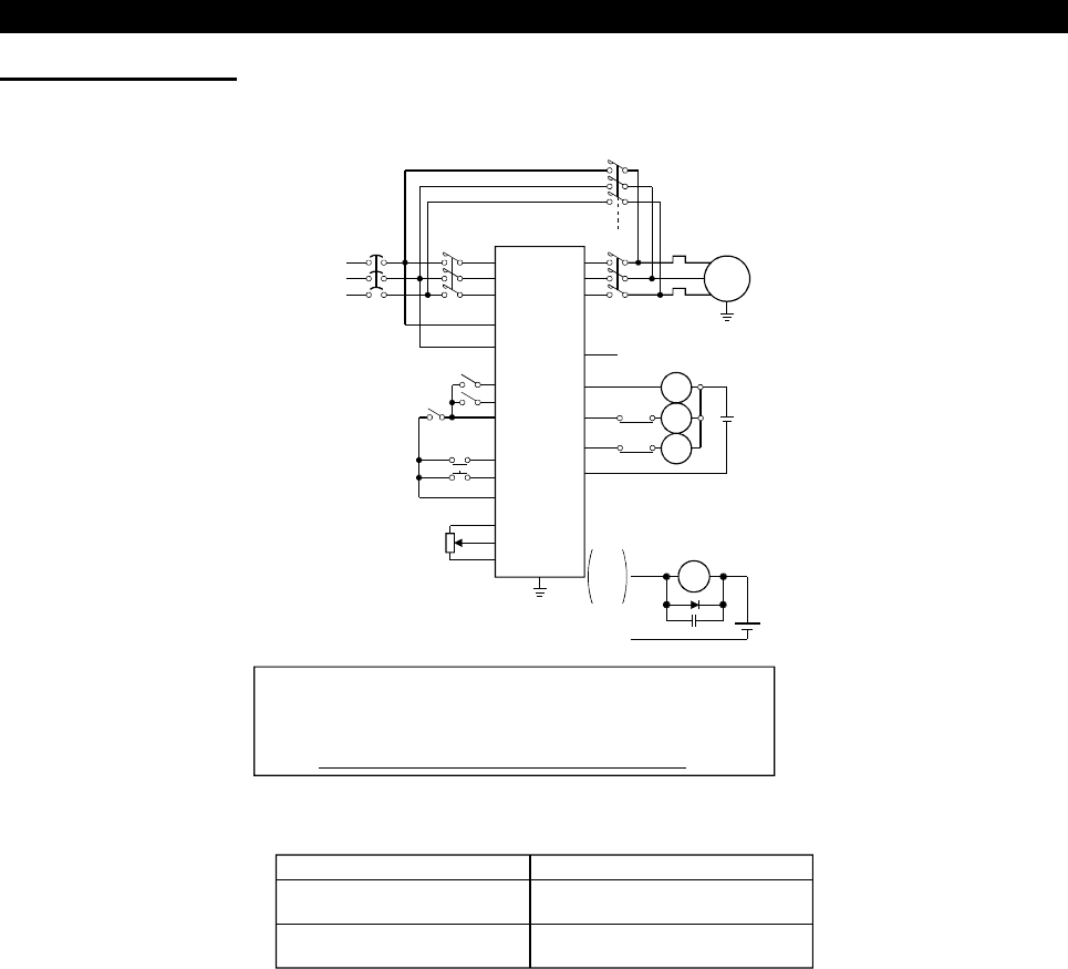
Wiring example
Sink logic, Pr. 185 = 7, Pr. 186 = 6, Pr. 192 = 17, Pr. 193 = 18, Pr. 194 = 19
*3. The terminals used depend on the Pr. 180 to Pr. 186 settings.
Note:
!
This switch-over function is used in the external operation
mode. Always connect terminals R1, S1 (L
11
, L
21
) to a
different power supply (power supply different from the one
for MC1) to ensure proper operation.
!
MC2 and MC3 must be mechanically interlocked.
*1. Note the sequence output terminal capacities. The terminals used
depend on the Pr. 190 to Pr. 194 settings.
Output Terminal Capacity Permissible Output Terminal Load
Inverter's open collector outputs
(IPF, OL, FU)
24VDC 0.1A
FR-A5AR (option output)
230VAC 0.3A
30VDC 0.3A
*2. When connecting an AC power supply, connect the FR-A5AR option
and use the contact output.
When connecting a DC power supply, install the following protective
diode.
MC1
R
〈
L
1
〉
S
〈
L
2
〉
T
〈
L
3
〉
STF
R1
〈
L
11
〉
S1
〈
L
21
〉
CS
MRS
RES
SD
10
2
5
U
V
W
MC2
×
MC3
IM
IPF
OL
SE
*1
*1
*1
*2
MC3
MC2
DC24V
MC
1
FU
NFB
MC
2
MC
3
*3
OH
SU
SE
DC
24V
Frequency setting signal
External
thermal relay
Signal set in Pr. 190 to Pr. 195
Inverter
External thermal relay
Reset
Operation interlock
Inverter start
(forward rotation)
Inverter-commercial
power supply switch-over
IPF
OL
FU


