


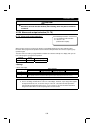
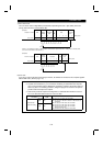
PARAMETERS
110
#
For the data codes of the parameters, refer to the data code list in the appendices.
REMARKS
For computer link operation, set the value "8888" as 65520 (HFFF0) and the value "9999" as 65535
(HFFFF).
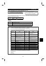
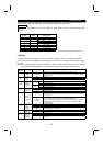
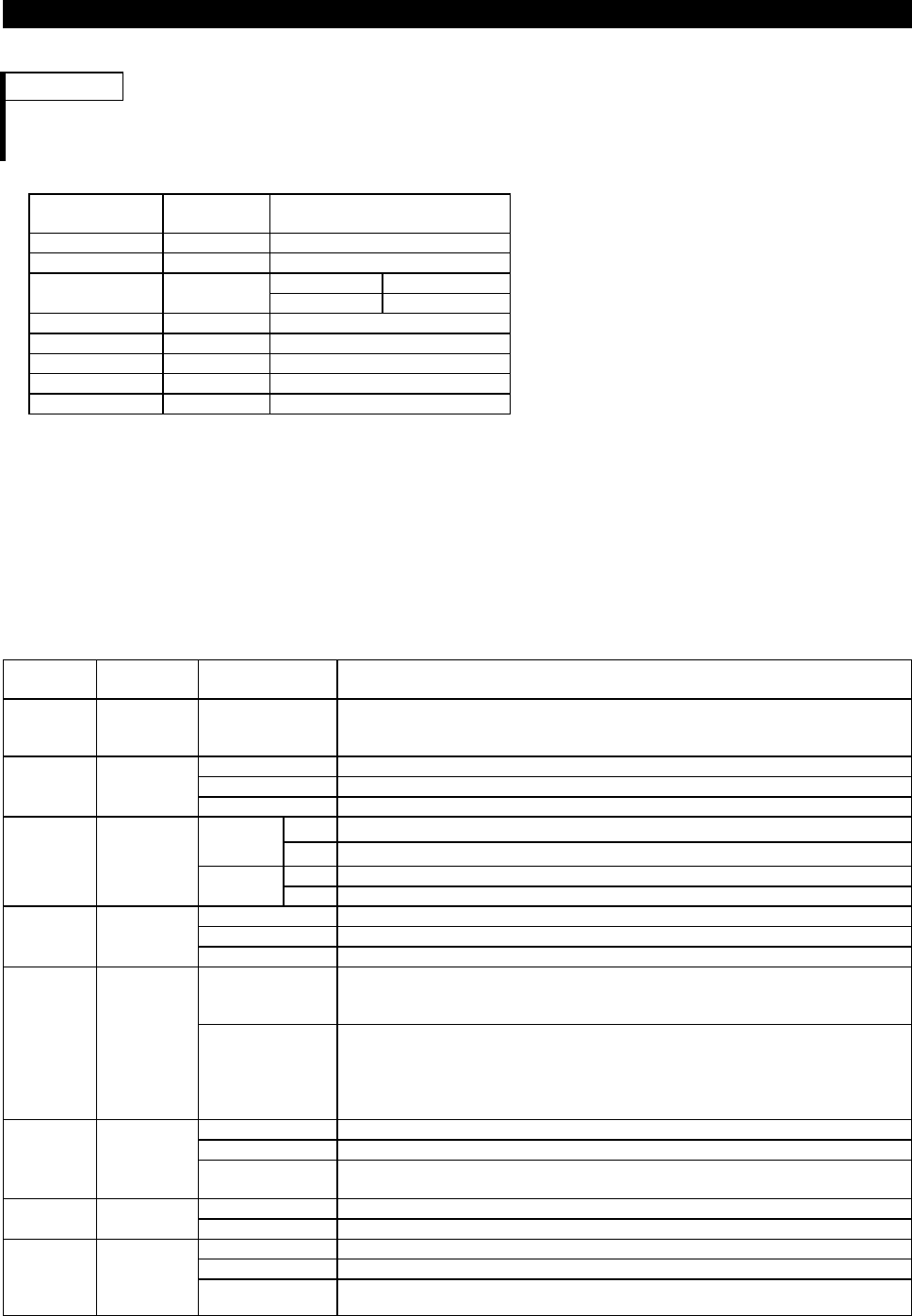
Parameter
Number
Factory
Setting
Setting Range
117 0 0 to 31
118 192 48, 96, 192
Data length 8 0, 1
119 1
Data length 7 10, 11
120 2 0, 1, 2
121 1 0 to 10, 9999
122* 0 <9999> 0, 0.1 to 999.8 s, 9999
123 9999 0 to 150ms, 9999
124 1 0, 1, 2
* To make communication, set any value other than 0 in Pr. 122 "communication check time interval".
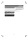
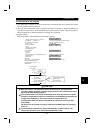
<Setting>
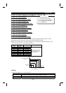
To make communication between the personal computer and inverter, the communication specifications
must be set to the inverter initially. If initial setting is not made or there is a setting fault, data transfer cannot
be made.
Note: After making the initial setting of the parameters, always reset the inverter. After you have changed the
communication-related parameters, communication cannot be made until the inverter is reset.
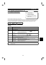
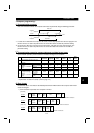
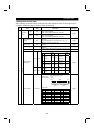
Parameter
Number
Description Setting Description
117
Station
number
0 to 31
Station number specified for communication from the PU connector.
Set the inverter station numbers when two or more inverters are connected to one
personal computer.
48 4800 bps
96 9600 bps118
Communi-
cation
speed
192 19200 bps
0 Stop bit length 1 bit
8 bits
1 Stop bit length 2 bits
10 Stop bit length 1 bit
119
Stop bit
length/data
length
7 bits
11 Stop bit length 2 bits
0 Absent
1 Odd parity present120
Parity check
presence/
absence
2 Even parity present
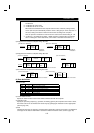
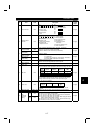
0 to 10
Set the permissible number of retries at occurrence of data receive error. If the
number of consecutive errors exceeds the permissible value, the inverter will come
to an alarm stop.
121
Number of
communica-
tion retries
9999
(65535)
If a communication error occurs, the inverter will not come to an alarm stop. At this
time, the inverter can be coasted to a stop by MRS or RES input.
During a communication error (H0 to H5), the minor fault signal (LF) is switched
on. Allocate the used terminal with any of Pr. 190 to Pr. 195 (output terminal
function selection).
0 No communication
0.1 to 999.8 Set the communication check time [s] interval.
122
Communi-
cation
check time
interval
9999
If a no-communication state persists for longer than the permissible time, the
inverter will come to an alarm stop.
0 to 150ms Set the waiting time between data transmission to the inverter and response.
123
Waiting
time setting
9999 Set with communication data.
0 Without CR
•
LF
1With CR
•
Without LF
124
CR
•
LF
presence/
absence
selection
2With CR
•
LF