


National Instruments™, NI™, and ni.com™ are trademarks ofNational Instruments Corporation. Productand company names mentionedherein are
trademarks or trade names of theirrespective companies.
322691B-01 Copyright © 2000, 2001 National Instruments Corp. All rights reserved. June 2001
USER GUIDE
MID-7654/7652 S
ERVO
P
OWER
M
OTOR
D
RIVE
This user guide describes the electrical and mechanical aspects of the
MID-7654/7652 servo power motor drive and describes how to use
the MID-7654/7652 with your motion controller.
Contents
Conventions ............................................................................................2
Introduction.............................................................................................2
What You Need to Get Started ...............................................................3
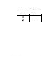
Safety Information ..................................................................................3
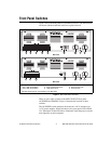
Front Panel Switches...............................................................................5
Host Bus Interlock Circuit ......................................................................6
Front Panel LEDs....................................................................................6
Amplifier Fault Output LEDs..........................................................7
Amplifier Inhibit LEDs....................................................................7
Limit Status LEDs ...........................................................................7
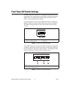
Front Panel DIP Switch Settings.............................................................8
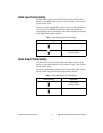
Inhibit Input Polarity Setting ...........................................................9
Inhibit Output Polarity Setting.........................................................9
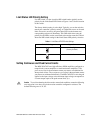
Limit Status LED Polarity Setting...................................................10
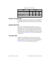
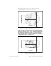
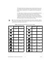
Setting Continuous and Peak Current Limits ..................................10
Setting Motor Inductance Levels.....................................................13
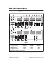
Back Panel Connector Wiring.................................................................15
Terminal Block Wiring....................................................................17
Servo Motor Power Terminal Blocks.......................................17
Rear Guard................................................................................19
Encoder Terminal Blocks.........................................................22
Limit Switch Terminal Blocks .................................................24
Breakpoint and Trigger Terminal Blocks.................................25
Analog I/O Terminal Blocks ....................................................25
Step and Direction Terminal Block..........................................26
Cable Installation for CE Compliance.............................................27
Accessories Included for Optional Use...................................................28
Strain-Relief Bar Installation...........................................................28
Panel Mount Kit Installation............................................................29