


© National Instruments Corporation 9 MID-7654/7652 Servo Power Motor Drive User Guide
Inhibit Input Polarity Setting
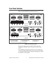
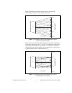
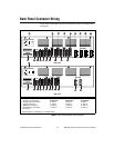
UseDIPswitch1onthe4-positionDIPswitchbanktogloballysetthe
polarity for the inhibit input for all axes. Refer to Figures 1 and 3 for the
location of this switch.
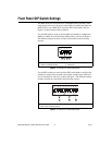
The factory-default setting of DIP switch 1 is active-low. If the inhibit input
is active, the axis is inhibited and the yellow status LED (middle row)
corresponding to that axis illuminates. Table 2 showsthe DIP switch setting
for the inhibit input polarity selection.
Inhibit Output Polarity Setting
UseDIPswitch2onthe4-positionDIPswitchbanktogloballysetthe
polarity for the inhibit output for all axes. Refer to Figures 1 and 3 for the
location of this switch.
The factory-default setting of DIP switch 2 is active-high. Table 3 shows
the DIP switch setting for the inhibit output polarity selection.
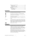
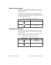
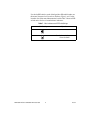
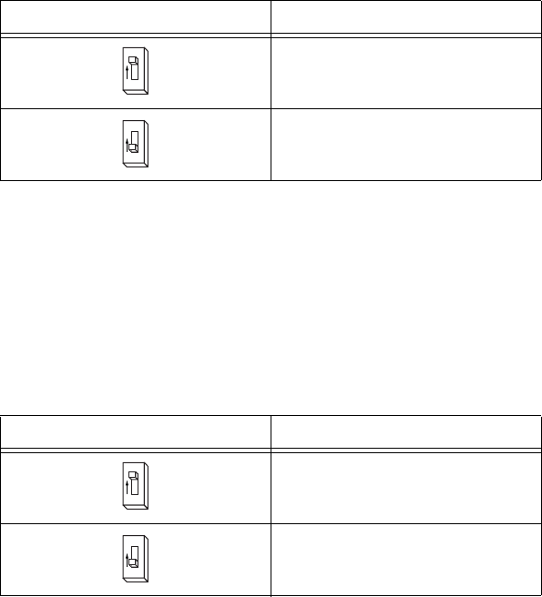
Table 2.
Inhibit Input Polarity DIP Switch Settings
Switch Setting Operation
Active-high
Active-low
(factory default)
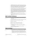
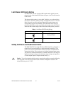
Table 3.
Inhibit Output Polarity DIP Switch Settings
Switch Setting Operation
Active-high
(factory default)
Active-low
1
O
N
1
O
N
3
O
N
3
O
N