


© National Instruments Corporation 7 MID-7654/7652 Servo Power Motor Drive User Guide
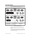
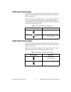
Amplifier Fault Output LEDs
The top row of the LED status array indicates the status of the amplifiers.
A red LED indicates an overcurrent condition, a short circuit condition, an
over temperature condition, or a problem withthe motor bus voltageon that
axis.
Amplifier Inhibit LEDs
The middle row of the LED status array indicates if a motor axis is
inhibited. An axis is inhibited and the LED illuminates yellow if the host
bus interlock circuitry is activated from the back panel, if the ENABLE
switch on the front panel is in the inhibit position, if the motion controller’s
inhibit signal is low, or if the per-axis inhibit input is actively driven. You
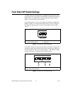
can select the polarity of the per-axis inhibit input from the front panel DIP
switches. See the Front Panel DIP Switch Settings section of this guide for
more information.
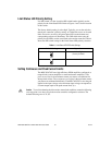
Limit Status LEDs
The bottom row of the LED status array indicates if a limit switch is
currently active. The LED illuminates green when either the forward or
reverse limit switch is active for each axis. You can select the polarity for
the limit status LEDs from the front panel DIP switches. See the Front
Panel DIP Switch Settings of this guide for more information.
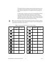
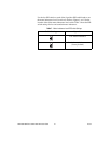
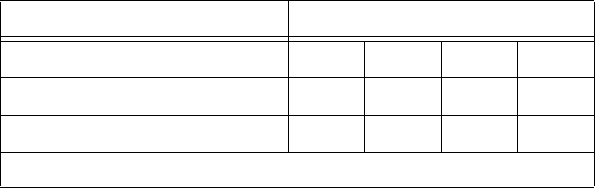
Table 1. Front Panel LED Indicators
Status Motor Axis
Amplifier Fault Output (red) 1 2 3
*
4
*
Amplifier Inhibit (yellow) 1 2 3
*
4
*
Limit Status (green) 1 2 3
*
4
*
*
These LEDs only appear on the MID-7654.