


© National Instruments Corporation 23 MID-7654/7652 Servo Power Motor Drive User Guide
Note
If you require other encoder power voltages, reference an external power supply to
the Digital Ground signal on the 8-pin encoder terminal block.
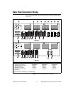
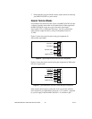
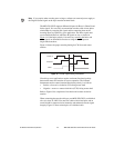
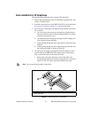
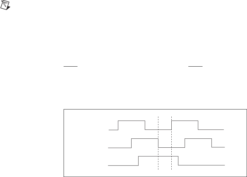
The MID-7654/7652 supports differential inputs for Phase A, Phase B, and
Index signals. You can easily accommodate encoders with various phase
relationships by swapping the signals and/or connecting them to the
inverting inputs as required by your application. The Index signal must
occur when both Phase A and Phase B signals are low, as shown in
Figure 14. If the Index polarity is inverted, try reversing the Index and
Index
signals on differential encoders or using the Index input on
single-ended encoders.
Figure 14 shows the proper encoder phasing for CW (forward) motor
rotation.
Figure 14. Encoder Signal Phasing, CW Rotation
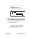
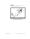
Closed-loop servo applications require consistent directional polarity
between the motor and encoder for correct operation. The National
Instruments motion control standard directional polarity is as follows:
• Positive = forward = clockwise (CW) facing motor shaft
• Negative = reverse = counter-clockwise (CCW) facing motor shaft
Refer to Figure 8 for a depiction of clockwise and counter-clockwise
rotation.
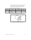
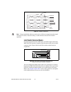
When connecting the encoder wiring to your MID-7654/7652, useshielded
wire of at least 24 AWG. You must use cables with twisted pairs and an
overall shield for improved noise immunity and enhanced encoder signal
integrity. Figure 15 shows twisted pairs in a shielded cable.
Phase A
Phase B
Index