


MID-7654/7652 Servo Power Motor Drive User Guide 26 ni.com
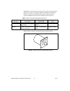
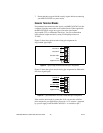
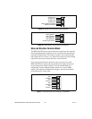
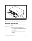
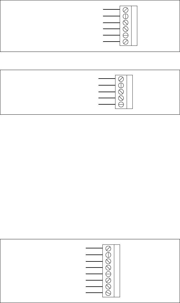
Figure 19. Analog Input Terminal Block Pin Assignment
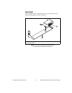
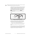
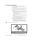
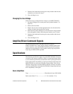
Figure 20. Analog Output Terminal Block Pin Assignment
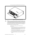
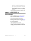
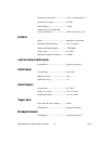
Step and Direction Terminal Block
The MID-7654/7652 passes step and direction signals from the controller
directly through the drive, allowing you to access them through the 8-pin
removable terminal block. This feature is useful if your system includes
both stepper and servo motors, as it reduces the amount of custom cabling
required to connect your motors and drives to the controller.
To use the step and direction connector, select an unused axis on the
MID-7654/7652 and connect the step and direction outputs for that axis
to your stepper drive. Refer to Figure 21 for the terminal block pin
assignments. Connect additional signals for the axis, such as inhibit
outputs, limit switches, breakpoints and triggers, and encoder feedback,
as described earlier in this guide.
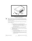
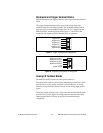
Figure 21. Step and Direction Terminal Block Pin Assignment
1
2
3
4
5
6
Analog Input 1
Analog Input 2
Analog Input 4
Analog Input Ground
Analog Input 3
Analog Reference (Output)
1
2
3
4
5
Analog Output 1
Analog Output 2
Analog Output 4
Analog Output 3
Analog Output Ground
1
2
3
4
5
6
7
8
Step 1
Direction 1
Direction 2
Direction 3
Step 2
Step 3
Direction 4
Step 4