


© National Instruments Corporation 17 MID-7654/7652 Servo Power Motor Drive User Guide
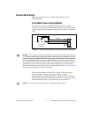
Terminal Block Wiring
This section describes how to wire the terminal blocks on your
MID-7654/7652.
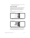
Servo Motor Power Terminal Blocks
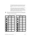
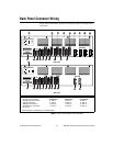
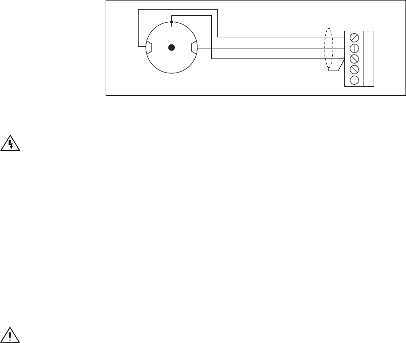
For motor power wiring, each MID-7654/7652 axis has a separate
5-position removable screw terminal block. Figure 7 shows a typical servo
motor configuration pin assignment. The dotted loop indicates a shielded
cable.
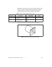
Figure 7.
Typical Servo Motor (DC Brush Type) Terminal Block Pin Assignment
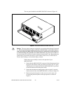
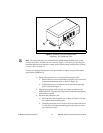
Warning
The servo motor connectors on this drive are energized when the unit is powered
on. The rear guard must be in place at all times while the unit is connected to a power
outlet. Disconnect the MID-7654/7652 unit from power outlet before connecting wires
to or disconnecting wires from the servo motor connectors. Strip back the insulation of
the servo motor wires to the servo motor connectors no more than 7 mm. Reattach the rear
guard before you reconnect the unit to a power outlet. Failure to do so could result in
electric shock leading to serious bodily injury or death. Refer to the Rear Guard section of
this guide for information on using the rear guard.
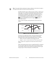
You should use shielded 20 AWG wire or larger for the motor power
cable. If available, connect a motor case ground wire to pin 3
(Ground/Shield) on the MID-7654/7652 as shown in Figure 7; this wire
helps avoid ground loops and signal noise problems.(Case ground connects
to the motor housing, not to any of the motor power terminals.)
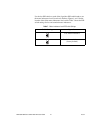
Caution
Never connect unused center taps or winding terminals to pin 3.
1
2
3
4
5
Motor +
Motor –
Motor Case Ground
+ –
Shield
Servo Motor