


MID-7654/7652 Servo Power Motor Drive User Guide 12 ni.com
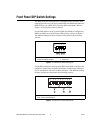
The amplifier peak and continuous current limits have been factory set for
5 A continuous current output and 10 A peak current output. Verify that
these settings are appropriate for your application before powering your
motors.
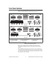
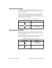
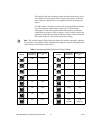
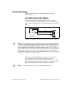
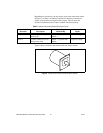
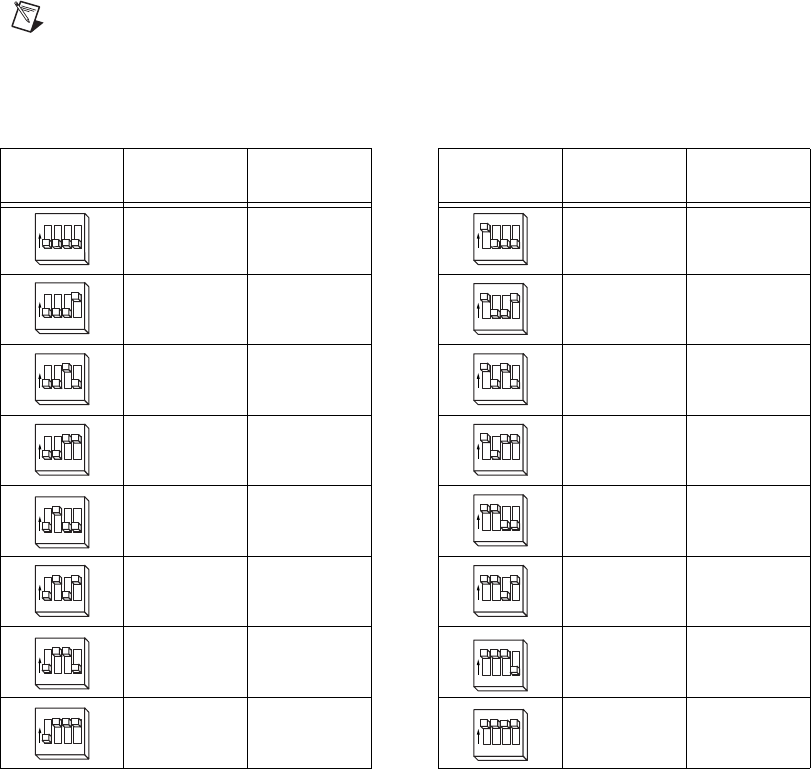
Use DIP switches 1 through 4 on each of the 9-position DIP switch banks
to set the continuous current limit for each axis. Use DIP switches
5 through 8 on each of the 9-position DIP switch banks to set the peak
current limit for each axis. Refer to Figures 1 and 3 for the location of the
continuous current limit and peak current limit switches. Table 5 shows the
DIP switch settings for all possible current limit settings.
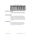
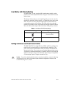
Note
The switches shown in Table 5 show the settings for switches 1 through 4, which are
the continuous current DIP switches. Configure the settings for switches 5 through 8 in the
same manner to set the peak current values.
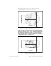
Table 5. Continuous and Peak Output Current DIP Switch Settings
Switch
Continuous
Current (A)
Peak Current
(A)
Switch
Continuous
Current (A)
Peak Current
(A)
5.00 10.00 1.25 2.50
4.50 9.00 1.15 2.30
3.80 7.55 1.10 2.20
3.00 6.00 1.05 2.10
2.45 4.90 1.00 1.95
2.10 4.20 0.95 1.85
1.95 3.85 0.90 1.80
1.70 3.45 0.85
(default)
1.70
(default)
1
O
N
234
1
O
N
234
1
O
N
234
1
O
N
234
1
O
N
234 1
O
N
234
1
O
N
234 1
O
N
234
1
O
N
234
1
O
N
234
1
O
N
234 1
O
N
234
1
O
N
234
1
O
N
234
1
O
N
234
1
O
N
234