


MID-7654/7652 Servo Power Motor Drive User Guide 8 ni.com
Front Panel DIP Switch Settings
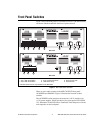
The MID-7654/7652 front panel has a detachable metal plate that, when
removed, provides access to one 4-positionDIP switchbank and eitherfour
(MID-7654) or two (MID-7652) 9-position DIP switch banks. Refer to
Figure 1 for the location of these switches.
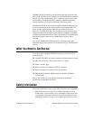
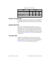
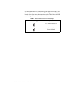
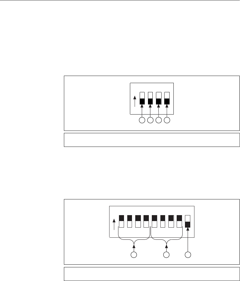
Use the DIP switches on the 4-position DIP switch bank to configure the
inhibit in, inhibit out, and limit status LED polarity as shown in Figure 2.
The different settings for these switches are described in the following
sections.
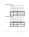
Figure 2. 4-Position DIP Switch Bank Layout
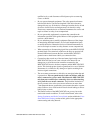
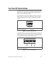
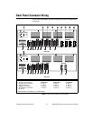
Use the DIP switches on each 9-position DIP switch bank to configure the
continuous current limit, the peak current limit, and the motor inductance
(low or standard) for each axis, as shown in Figure 3. The different settings
for these switches are described in the following sections.
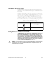
Figure 3. 9-Position DIP Switch Bank Layout
1 Inhibit In Polarity Switch
2 Inhibit Out Polarity Switch
3 Limit Status LED Polarity Switch
4 Reserved
1 Continuous Current Limit Switches
2 Peak Current Limit Switches
3 Motor Inductance Switch
1234
O
N
1 2 3 4
123456789
O
N
1 2
3