


MID-7654/7652 Servo Power Motor Drive User Guide 28 ni.com
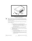
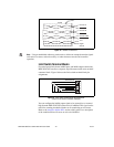
b. Lay the cables so that the braided shield makes full contact with
the foam of the strain-relief bar. The braided shield must only
make contact with the strain-relief bar, and no other part of the
device.
c. Lower the clamp and tighten the thumb nuts to remove all gaps
between the foam and the cable shields. The foam should press
around the shield of the cable to provide 360-degree grounding to
the cable shield.
5. Ground the braided shield at the opposite end of the cables to your
destination enclosure ground.
Accessories Included for Optional Use
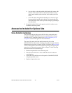
Strain-Relief Bar Installation
The strain-relief bar provides strain relief for wiring to the back panel
terminals of the MID-7654/7652. It must be used to provide necessary
grounding for CE compliance. Refer to the Cable Installation for CE
Compliance section of this guide for more information.
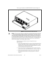
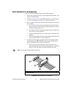
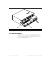
The arms of the strain-relief bar attach between the sides of the
MID-7654/7652 and the bottom mounting plate of the rear guard with the
thumb nuts facing upwards, as shown in Figure 23. Refer to the Rear Guard
section of this guide for more information on removing and replacing the
protection cover from the rear guard. Refer to Figure 23 while following
these strain-relief bar installation steps:
1. Remove the protection cover of the rear guard.
2. Place the strain-relief bar so it fits within the sides of the bottom
mounting plate.
3. Attach the strain-relief bar to the side panels of the MID-7654/7652
using the provided screws.
4. Replace the protection cover.