


© National Instruments Corporation 27 MID-7654/7652 Servo Power Motor Drive User Guide
Cable Installation for CE Compliance
Take the following additional steps to ensure CE Compliance:
1. Enclose the terminal block wires in a 360-degree shielded cable. This
requires a braided shield.
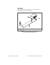
2. Install the strain-relief bar on the MID-7654/7652 as described in the
Accessories Included for Optional Use section of this guide.
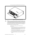
3. Place all cables connecting to the back panel through the strain-relief
bar, as follows:
a. All servo motor cables must pass through the far right clamp on
the strain-relief bar, which is directly aligned with the servo motor
terminals and protection cover.
b. All remaining cables should pass through the three clamps to the
left of the servo motor terminals.
c. Cables passing through the same clamp must be of the same cable
diameter.
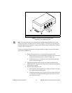
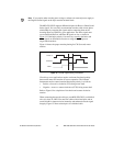
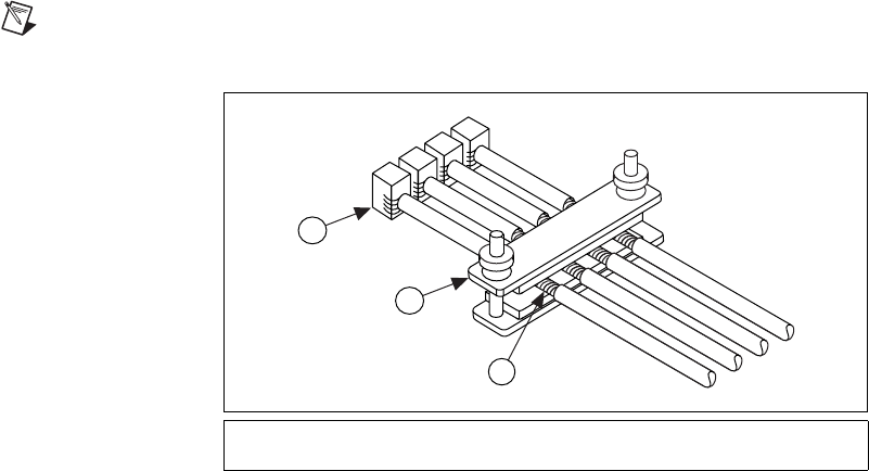
d. Cables passing through the same clamp must be parallel and must
not overlap each other, as shown in Figure 22.
4. All cables must be properly grounded to the strain-relief bar, which
grounds them to the MID-7654/7652 chassis ground. Follow these
steps to ground the cables to the strain-relief bar:
a. Remove the outer jacket from the section of the cable to be
inserted between the strain-relief bar clamp and foam, as shown in
Figure 22. This will expose the braided shield of the cable.
Note
Do not cut the braided shield of the cable.
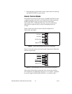
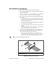
Figure 22. Required Cabling for CE Compliance
1 Braided Shield of the Cable
2 Strain Relief Bar
3 Terminal Block Connector
2
3
1