


MID-7654/7652 Servo Power Motor Drive User Guide 6 ni.com
The ENABLE switch enables or inhibits the servo amplifiers. If the
ENABLEswitch is in the inhibit position(OFF), the amplifieroutput stages
are inhibited and the yellow LEDs for all axes illuminate. See the Front
Panel LEDs section of this guide for more information.
Both the AC POWER and ENABLE switches can inhibit the servo
amplifiers. However, as longas theAC POWER switch is on, only the servo
amplifier output stages are disabled. The remaining circuitry remains
active, including the quadrature encoder circuit.
Warning
Yo u must change the MID-7654/7652 main input fuse on the rear panel if you
change the line voltage from the factory setting. Refer to the Specifications section of this
guide for fuse specifications. Refer to the Modifying the Power Entry Module section for
moreinformationonhandlingthepowerentrymodule.
Host Bus Interlock Circuit
The MID-7654/7652 has a host bus interlock circuit that monitors the
presence of +5 V from the host computer and disables the MID-7654/7652
when the voltage is not present or falls out of tolerance. This circuit shuts
down the servo amplifiers for all axes by activating the inhibit when the
host computer is disconnected from the MID-7654/7652 or inadvertently
shut down. Activation of the host bus interlock circuitry illuminates the
yellow LEDs (middle row) of the LED status array for all axes. See the
FrontPanelLEDssection of this guide for more information.
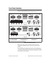
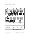
Front Panel LEDs
The front panel LEDs consist of a single green LED to indicate if the main
5 V power is active. If the DC power supplies are active, the green power
LED illuminates. If this LED fails to illuminate, check the power cord and
the main input fuse on the front panel.
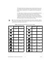
An LED status array of 3 rows by 4 columns on the MID-7654 or 3 rows
by 2 columns on the MID-7652 provides a variety of status information.
Refer to Figure 1 for the location of the front panel LEDs. The LED status
array is arranged by motor axes. Each of the four columns represents an
axis, and each of the three rows represents a particular status. Table 1
summarizes the axes and statuses to which the different LEDs in the 3 × 4
or 3 × 2 array correspond.