


© National Instruments Corporation 5 MID-7654/7652 Servo Power Motor Drive User Guide
Front Panel Switches
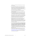
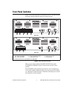
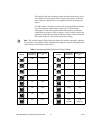
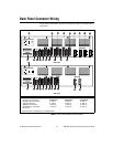
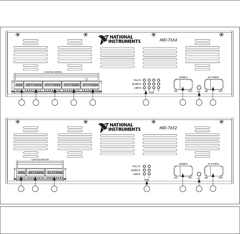
Figure 1 shows the front panel for your MID-7654/7652. The DIP switches
are shown with the detachable metal cover plate removed.
Figure 1. MID-7654/7652 Front Panel
There are two rocker switches on the MID-7654/7652 front panel:
AC POWER and ENABLE. Figure 1 illustrates the location of these
switches.
The AC POWER switch energizes the motor bus (+48 V) and the logic
(+5 V) power supplies. When switched on, the green power LED labeled
+5 V illuminates. If this LED fails to illuminate, check the power cord and
main input fuse on the back panel.
1 Polarity DIP Switch Bank
2 Axis 1 DIP Switch Bank
3 Axis 2 DIP Switch Bank
4Axis3DIPSwitchBank*
5Axis4DIPSwitchBank*
6 LED Status Array
7 Enable Switch
8 Green Power LED
9 Power Switch
* This DIP switch bank is only available on the MID-7654.
8
7
4 Axis Servo Motor Drive
9
6
6
MID-7654
MID-7652
8
7
9
21 3 4 5
POL AXIS 1 AXIS2 AXIS 3 AXIS 4
21 3
POL AXIS 1 AXIS 2
4 Axis Servo Motor Drive
2 Axis Servo Motor Drive