


MID-7654/7652 Servo Power Motor Drive User Guide 10 ni.com
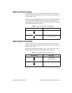
Limit Status LED Polarity Setting
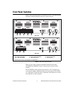
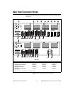
UseDIPswitch3onthe4-positionDIPswitchbanktogloballysetthe
polarity for the Limit Status LED. Refer to Figures 1 and 3 for the location
of this switch.
The factory-default setting is active-high. Typically, you set the switch to
match your controller’s polarity setting, so if either the reverse or forward
limits for an axis are active, the green status LED (on the bottom row)
corresponding to that axis illuminates. This DIP switch alters only the
polarity for the LEDs, not the actual limit to the motion controller. Table 4
shows the DIP switch setting for the Limit Status LED polarity selection.
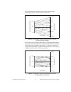
Setting Continuous and Peak Current Limits
The MID-7654/7652 uses high-efficiency PWM amplifiers configured as
torque blocks (current amplifiers or transconductance amplifiers). The
peak current limit is the maximum current your motor can withstand for
short periods of time. The continuous current limit is the maximum current
your motor can withstand indefinitely. The MID-7654/7652 varies the gain
applied to the input voltage so the maximum input voltage corresponds to
a current output equal to the peak current limit, I
peak
.
Caution
To avoid overheating the drive under amotor fault condition, ensure the following
error trip point is set above zero in the motion controller configuration software. The
default following error is 32,767.
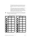
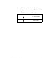
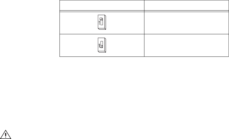
Table 4. Limit Status LED DIP Switch Settings
Switch Setting Operation
Active-high
(factory default)
Active-low
2
O
N
2
O
N