


MID-7654/7652 Servo Power Motor Drive User Guide 22 ni.com
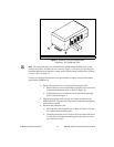
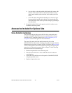
7. Ensure thatthe rear guard is heldsecurely in place beforereconnecting
your MID-7654/7652 to a power outlet.
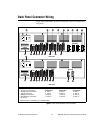
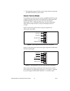
Encoder Terminal Blocks
For quadrature incremental encoder signals, each MID-7654/7652 axis has
a separate 8-position removable screw terminal block. Where applicable,
the MID-7654/7652 accepts two types of encoder signal inputs:
single-ended (TTL) or differential line driver. You can accommodate
open-collector output encoders by using 2.2 kΩ pullup resistors to
+5 VDC.
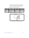
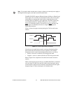
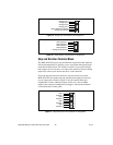
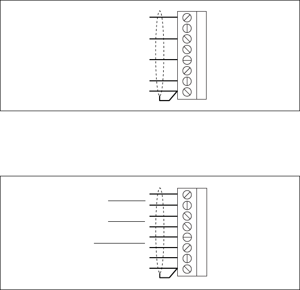
Figure 12 shows the typical encoder wiring pin assignment for
single-ended signal input.
Figure 12. Typical Single-Ended Encoder Wiring Pin Assignment
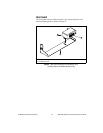
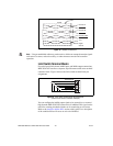
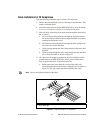
Figure 13 shows the typical encoder wiring pin assignment for differential
line driver signal inputs.
Figure 13. Typical Differential Line Driver Encoder Wiring Pin Assignment
If the encoder cable length is greater than 10 ft, use encoders with line
driver outputs for your applications. Power for a +5 V encoder—generated
by a power supply inside the MID-7654/7652—is available on pin 7.
1
2
3
4
5
6
7
8
Encoder A
Encoder B
Encoder Index
+5 V
Digital Ground
1
2
3
4
5
6
7
8
Encoder A
Encoder A
Encoder B
Encoder B
Encoder Index
Encoder Index
+5 V
Digital Ground