9-18
Chapter 9 MXYX
4-2 Whipover cable type
!
CAUTION
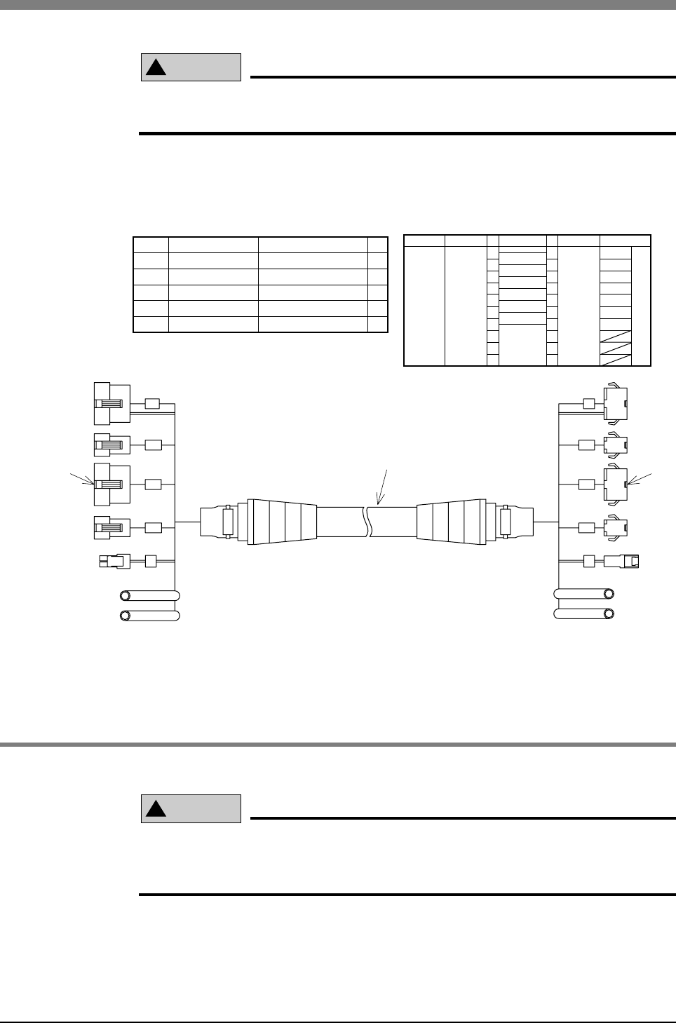
Do not clamp the wires or tubes to the outside of the independent cable. The
independent cable could sag or break and ultimately be disconnected.
The signal wires (0.3mm
2
× 7 wires) and air tubes (4 × 2.5, 2 tubes) are incorpo-
rated in the Whipover cable. Use these to wire and pipe to the tool.
Part No.
1
2
3
4
5
SM connector
SM connector
Contact
Contact
Cable
SMR-10V-B
SMP-10V-BC
SYM-001T-0.6
SHF-001T-0.8BS
Qty.
1
1
7
7
1
Part name Part No.
Signal
General-
purpose
I/O
Remarks
NO
1
2
3
4
5
6
7
8
9
10
NO
1
2
3
4
5
6
7
8
9
10
Connector
I/O
q
Connector
I/O
w
Brown
Red
Orange
Blue
Purple
Gray
White
I/O
P
BK
BK
M
P
I/O
YZ
M
R
ZRY
ORG
ORG
Controller side
Air tube
Air tube
qe
wr
t
Tool side
Fig. 9-16 Whipover cable user-wire specifications
4-2-1 Examples of wiring and piping with Whipover cable
!
CAUTION
Securely crimp the pin and insert into the pin connector.
Failure to do so will prevent the signals and power from being supplied cor-
rectly, and may prevent the device from operating correctly.
1) Crimp the user's cable and tool wiring onto the enclosed connector.
Refer to section “1-2. User I/O wire” in Chapter 5 “Specifications” for de-
tails on the enclosed connector and pin specifications.
Recommended crimping tool YC-122R (J.S.T. Mfg Co., Ltd.)


