


CHAPTER 4: INSTALLATION
28
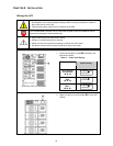
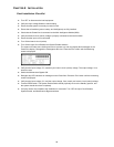
Final Installation Checklist
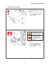
Turn OFF or disconnect the load equipment.
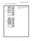
Verify the Input Voltage Selection switch setting.
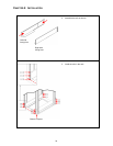
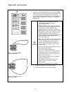
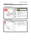
Ensure that the system is securely mounted in rack.
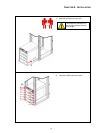
Ensure that all modules (power, battery, and intelligence) are fully installed.
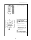
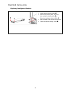
Check that the PowerView is connected to the Main Intelligence Module (MIM).
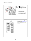
Verify that branch circuit (mains) voltage is properly connected to the terminal block.
Ensure that the input cord is connected.
Turn ON the branch circuit (mains).
Turn ON the Input Circuit Breaker and System Enable switches.
The system will make some clicking sounds as it powers up, and may display fault messages on the
PowerView display. Disregard the messages at this time. Press the ‘Esc’ button until the Monitoring
screen is displayed.
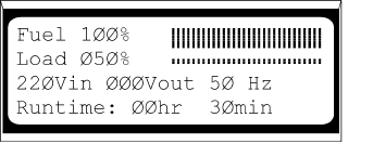
Verify that the input voltage, Vin, matches your branch circuit (mains) voltage. The output voltage, Vout,
should be zero.
Switch the Maintenance Bypass ON.
Disregard any LED indicators or messages on the PowerView. Press the ‘Esc’ button until the monitoring
screen is displayed.
Verify that the input voltage, Vin, and the output voltage, Vout, match your branch circuit (mains) voltage.
Test the REPO switch. The System Enable switch should physically move to the Standby position, and
the system should shut down completely.
If all prior checks are completed, the installation is successful. Turn OFF the Input Circuit Breaker,
System Enable, and Maintenance Bypass switches.