


1-4
Cisco CRS-1 Carrier Routing System 8-Slot Line Card Chassis Site Planning Guide
OL-5802-06
Chapter 1 Cisco CRS-1 Carrier Routing System
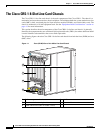
The Cisco CRS-1 8-Slot Line Card Chassis
–
10-Gigabit Ethernet (GE. Available in long-reach (LR) optics. This PLIM supports pluggable
optics, and can be configured with 1 to 8 ports.
–
Cisco CRS-1 SPA Interface Processor-800. Occupies one physical-layer-interface-module
(PLIM) slot on the Cisco CRS-1 16- and 8-Slot Line Card Chassis. Supports six normal-height
SPAs or three double-height SPAs or any combination in between.
• A chassis midplane. The midplane connects MSCs to their associated PLIMs and allows an MSC to
be removed from the chassis without having to disconnect the cables that are attached to the
associated PLIM. The midplane distributes power, connects the MSCs to the switch fabric cards,
and provides control plane interconnections. The midplane is not field replaceable by the customer.
• One or two route processor cards (RPs). The RPs provide the intelligence of the system by
functioning as the line card chassis system controller and providing route processing. Only one RP
is required for system operation. For redundant operation, you can order a second, redundant RP as
an option (CRS-8-RP/R). When two RPs are used, only one RP is active at a time. The second RP
acts as a “standby” RP, serving as a backup if the active RP fails.
The RP also monitors system alarms and controls the system fans. LEDS on the front panel indicate
active alarm conditions.
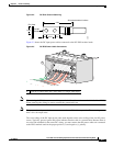
• Upper and lower fan trays. The fans pull cool air through the chassis. A removable air filter is
located below the PLIM card cage at the front of the chassis. Each fan tray contains three fans.
• Four half-height switch fabric cards. These cards provide the three-stage Benes switch fabric
(S1/S2/S3) for the routing system. The switch fabric performs the cross-connect function of the
routing system, connecting every MSC (and its associated PLIM) with every other MSC (and its
associated PLIM) in the system.
The switch fabric receives user data from one MSC and PLIM pair and performs the switching
necessary to route the data to the appropriate egress MSC and PLIM pair. The switch fabric is
divided into eight planes that evenly distribute the traffic across the switch fabric. Each switch fabric
card implements two planes of the switch fabric.
• A power system that provides redundant power to the chassis. The power system consists of two
AC
or DC power distribution units (PDUs) and two AC rectifier modules or two DC power entry
modules (PEMs), one for each PDU. Each PDU supplies input power to a rectifier or PEM, which
in turn provides processed power to the chassis. Each DC and AC power module contains a
removable air filter, located on the back of the module.
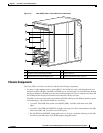
The PLIM side of the chassis is considered the front of the chassis, where user data cables attach to the
PLIMs and cool air enters the chassis. The MSC side, which is where warm air is exhausted, is
considered the rear of the chassis.
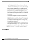
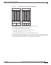
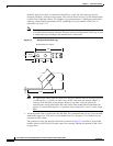
Chassis Slot Numbers
The following figure shows the slot numbers on the front and back of the chassis.