


4-5
Cisco CRS-1 Carrier Routing System 8-Slot Line Card Chassis Site Planning Guide
OL-5802-06
Chapter 4 Site Planning Considerations
Aisle Spacing and Maintenance Access Floor Plan
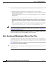
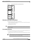
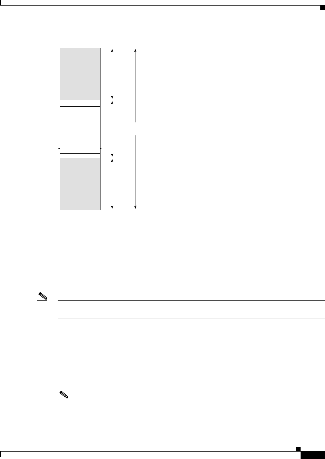
Figure 4-2 Typical Cisco CRS-1 8-Slot Line Card Chassis Floor Plan
Dimensions of the 8-Slot Line Card Chassis
The dimensions for the Cisco CRS-1 8-slot line card chassis are:
• Chassis depth (including closed (optional) front and rear doors and an installed cable management
bracket): ~35 to 40 in. (88.9 to 101.6 cm)
• Chassis height: 38.5 in. (97.8 cm)
• Chassis width: 17.5 in. (44.5 cm).
Note Because there is no external switch-fabric interconnection cabling on a single line card chassis system,
the rear door is optional.
Front and Rear Clearances
The site requires the following front and rear clearances for chassis installation and maintenance access:
• To install the chassis in the equipment rack: 40.4 inches (102.6 cm)
• To service components and allow system airflow (both in front of and behind the chassis): 36 inches
(91.4 cm)
Note Maintain at least 6 inches (15.2 cm) of clearance at both the inlet and exhaust openings on the
chassis and on the power modules to allow sufficient airflow.
122051
Service access
area: in front
of chassis
Service access
area: behind rear
of chassis
Cisco CRS-1 8-slot
line card chassis
112.4 in.
(285.4 cm)
40.4 in.
(102.6 cm)
36 in.
(91.4 cm)
36 in.
(91.4 cm)