


Index
IN-3
Cisco CRS-1 Carrier Routing System 8-Slot Line Card Chassis Site Planning Guide
OL-5802-06
interface cables 4-7
product IDs (table) B-3
supported 1-3
ports, CONSOLE and AUX 4-6
power
cables 2-6, 2-9
power system 2-1
redundancy 2-1, 2-6
requirements 2-2, 2-9
specifications 3-1
specifications (table) 3-1
product IDs
chassis components B-1
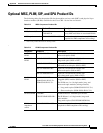
MSCs and PLIMs B-3
R
rack, See equipment rack
requirements
AC power 2-6
airflow 2-11
airflow exhaust 2-10
cooling 2-10
DC power 2-3
equipment rack 4-3
NEBS supplemental bonding and grounding 2-9
power cables 2-6, 2-9
RP cables 4-7
safety extra-low voltage (SELV) 2-3
routing system
AC power 2-6
air filter 2-10
airflow and exhaust 2-10
chassis midplane 1-4
clearances 4-4, 4-5
components 1-2
cooling 2-10
DC power 2-3
equipment rack 4-3
front and back 1-4
overview 1-1
physical dimensions 3-3
PLIM types 1-3
power and grounding 2-2, 2-9
power requirements 3-1
product IDs B-1
slot numbers 1-4
switch fabric cards 1-4
weight 3-3
See also chassis
S
safety extra-low voltage (SELV) requirements 2-3
service access clearance distance 4-5
shock, specifications 3-6
site planning
checklists A-1
considerations 4-1 to 4-8
site survey, sample (table) A-2 to A-5
slot numbers, chassis (figure) 1-4
SPA Interface Processor-800
product ID B-4
specifications
AC power 3-2
DC power 3-2
environmental 3-6
equipment rack (table) 3-3
power 3-1
switch fabric cards 1-4
system console 4-6
T
Tables
chassis and power specifications 3-1
chassis product IDs B-1
environmental specifications 3-6