


3-4
Cisco CRS-1 Carrier Routing System 8-Slot Line Card Chassis Site Planning Guide
OL-5802-06
Chapter 3 Technical and Environmental Specifications
Equipment Rack Specifications
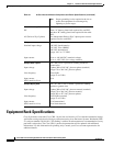
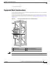
Load (weight) rating The rack must support the following weights and specifications:
• 650 lb (294.8 kg) single chassis with full cosmetics
• 1300 lb (589.7 kg) two chassis, each with full cosmetics
• 95 lb (43.0 kg) or more for each chassis for cabling
• Additional weight of other components in rack
Note ANSI specification T1.336 (2003), which defines static load
and safety margins, recommends that racks be designed to
support at least two times the anticipated load.
Note See ANSI specification T1.329 (2002) for dynamic load
requirements and earthquake resistance specifications.
Chassis and rack footprint
(floor contact area)
5.9 sq. ft (0.55 sq. m), 23.6 in. rack width by 36 in. chassis length
Maximum floor loading 600 lb/4.5 sq. ft = 133 lb/sq. ft (without cosmetics or doors)
272.2 kg/4134.2 sq. cm = .07 kg/sq. cm
650 lb/4.9 sq. ft = 132.7 lb/sq. ft (with cosmetics and doors)
294.8 kg/4580.1 sq. cm = .06 kg/sq. cm
Note Be sure to include the weight of the rack when you consider
floor loading requirements. The above numbers do not
include rack weight.
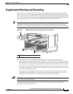
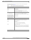
Rack Anchoring
General considerations • The rack must be bolted to the floor. For more information, see
the Cisco CRS-1 Carrier Routing System Line Card Chassis
Unpacking, Moving, and Securing Guide.
• Consider floor and overhead anchoring requirements for the site,
and size and load capacity of anchors and floor structure.
• Make sure that floor mounting bolts are accessible, especially if
annual retorquing of bolts is required.
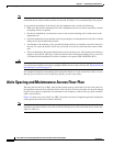
Floor mounting holes • Outrigger L-brackets:
20.1-inch (51.0 cm) wide x 31.6-inch (80.3 cm) deep
• Internal frame holes:
17.625-inch (44.77 cm wide) x 21-inch (53.34 cm) deep
• For all other racks, check with rack manufacturer.
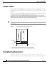
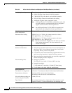
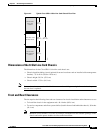
Chassis Clearances
Two chassis in a single rack 0.5-inch (1.27 cm) between chassis for horizontal shelf brackets
Front and rear of chassis 40.4-inch (102.6 cm) for chassis installation
36-inch (91.4 cm) for service access and airflow
Inlet and exhaust openings on
chassis and power modules
6-inch (15.2 cm)
Top of chassis No overhead clearance for a single chassis. Two chassis in a rack
requires 0.5-inch (1.27 cm) between chassis for mounting rails.
Table 3-2 8-Slot Line Card Chassis and Equipment Rack Specifications (continued)