


2-3
Cisco CRS-1 Carrier Routing System 8-Slot Line Card Chassis Site Planning Guide
OL-5802-06
Chapter 2 Power and Cooling
DC Power Requirements
DC Power Requirements
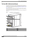
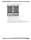
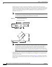
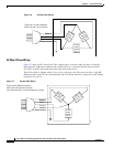
A DC-powered line card chassis contains two DC-input power distribution units (PDUs) and two DC
power entry modules (PEMs). Each DC PDU is connected to three DC power inputs and contains a single
7500-watt DC PEM that is field replaceable. Input DC power enters the PDU and is passed to the PEM,
which provides power to the components in the chassis. Each PEM has its own circuit breaker.
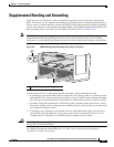
In addition to the requirements described in the “General Power and Grounding Requirements” section
on page 2-2, DC input power requirements are as follows:
• A DC-powered chassis requires 8,000 watts of DC input power.
• Each DC PDU requires three VDC inputs of –48/–60 VDC (nominal). The PDU accepts input
DC
power in the range –40.5 to –75 VDC.
• A DC-powered chassis requires access to the “A” and “B” power buses at the central office (CO).
This dual connectivity provides 2N power redundancy in case a power source fails.
–
One PDU should be connected to three –48/–60 VDC inputs from the central office “A” power
bus.
–
The other PDU should be connected to three –48/–60 VDC inputs from the “B” power bus.
• Required input current is as follows:
–
60 amps at nominal input voltage (–48/–60 VDC)
–
66 amps at low input voltage (–40.5 VDC).
• All power connection wiring must conform to the rules and regulations in the National Electrical
Code
(NEC) and any local codes. In addition, make sure that the wiring conforms to any internal
requirements at the installation site.
• Each DC power source must comply with the safety extra-low voltage (SELV) requirements in
UL
60950-1, CSA-C22.2 No. 60950-1, EN60950-1, AS/NZS 60950, and IEC60950-1.
• A DC-powered system should be installed in a restricted access area in accordance with the
National
Electric Code, ANSI/NFPA 70.
• All components in the area where DC input power is accessible must be properly insulated.
• A readily accessible two-pole disconnect device must be incorporated in the fixed wiring, unless it
is possible to rely on the identification of the power return conductor that is earth-grounded in the
DC power system.
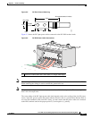
DC Input Power and Ground Cables
Each PDU has three sets of double-stud terminals (RTN, –48V/–60V) for connecting DC input power.
To
provide 2N power redundancy, one PDU should be connected to the central office “A” power bus
and the other PDU should be connected to the “B” power bus.
The requirements for the DC input power and ground connections are as follows:
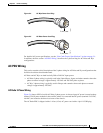
• For DC input power cables, select the appropriate wire gauge based on the National Electrical
Code
(NEC) and local codes for 60-amp service at nominal DC input voltage (–48/–60 VDC).
Three
pairs of cable leads, source DC (–) and source DC return (+), are required for each PDU.
These
cables are available from any commercial cable vendor. All input power cables for the chassis
should have the same wire gauge and cable lengths should match within 10 percent of deviation.