


A-4
Cisco CRS-1 Carrier Routing System 8-Slot Line Card Chassis Site Planning Guide
OL-5802-06
Appendix A Site Planning Guidelines
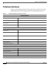
Preliminary Site Survey
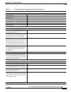
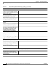
Power
Is DC or AC power available for each
chassis? Is there a connection point on the
panel for each chassis?
Is a fuse access panel (FAP) available for
the equipment? Provide a connection
point on the FAP for each chassis.
Will an FAP be installed in time for the
routing system installation? Provide a
date when the FAP will be installed.
Is the FAP located in the same room as the
chassis?
Is there an AC power outlet (220 V or
110
V) located within 10 feet of each
chassis, for PCs and test equipment?
Has proper grounding been provided for
the equipment? If not, when will the
grounding be available? Provide a
connection point for the grounding.
Are there any restrictions about when the
equipment can be powered on or when
electrical work can be done? If so,
describe them.
Are there special requirements for power
or power cables (for example, a different
gauge of wire)? If so, describe them.
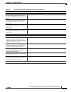
Air Conditioning
Does the site have the air conditioning
capacity to handle the routing system? If
not, note what will be done to rectify the
lack of adequate cooling.
Describe the air conditioning at the site.
Control Plane and Alarm Interfaces
Will the chassis be connected to an
external alarm system? Has the cabling
been considered?
Table A-2 Sample Routing System Preliminary Site Survey (continued)
Preliminary Site Survey