


3-5
Cisco CRS-1 Carrier Routing System 8-Slot Line Card Chassis Site Planning Guide
OL-5802-06
Chapter 3 Technical and Environmental Specifications
Equipment Rack Specifications
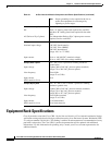
Equipment Rack Specifications (continued)
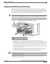
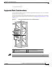
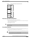
Mounting Rails and Hardware
Rail openings (aperture) • 17.75 in. (45.1 cm), side to side
• 22.8 in. (57.9 cm), front to back (adjustable or fixed)
Horizontal mounting rails The equipment rack should contain horizontal mounting rails to
place the chassis on. The mounting rails, which must be able to hold
at least 650
lb (294.8 kg), support the weight of the chassis.
• ESW 27 racks are equipped with horizontal mounting rails
already installed. Place the chassis on these rails.
• For other types of racks, a set of brackets is included in the
chassis installation kit, which is available as an option
(CRS-8-INSTALL-KT=). Install these brackets and place the
chassis on them. For details, see the Cisco CRS-1 Carrier
Routing System Line Card Chassis Unpacking, Moving, and
Securing Guide.
Note In addition to supporting the chassis, the mounting rails are
also designed to space adjustable rack rails at 22.8-inches (front
to back) for chassis installation.
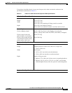
Mounting holes EIA standard mounting-hole spacing:
• 18.25-inches to 18.31-inches (46.36 to 46.51 cm),
center-to-center horizontal spacing
• 0.5 + 0.625 + 0.625-inches (1.27 + 1.59 + 1.59 cm),
vertical-hole-spacing pattern; repeats on 1.75-inch (4.45 cm)
pitch ETSI racks have mounting rails with EIA standard
spacing.
Mounting screws • 48 screws for each chassis, 12 screws in each of 4 vertical rails,
installed in holes with tick marks
• No. 10-32 screws (provided with the chassis)
• No. 10-24 or M5 screws can be used if rack thread pitch allows.
Note If you plan to use mounting screws other than the ones
shipped with the chassis, make sure that the screws are made
of stainless steel or a hard alloy. Do not use screws made of
soft
alloy steel.
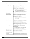
Compliance
Make sure that the rack complies with all appropriate standards for
your geographical area—for example, NEBS Seismic Zone 4
(GR-63-CORE, Sections 4.4.1 and 4.4.2).
Note The 8-slot chassis has passed Cisco Zone 4 seismic testing in
an ESW 27 rack (part
number F-01941-01).
Additional Rack Considerations
Interface cables When choosing a rack, consider cabling needs (chassis front). Allow
at least 95 lb (43.1 kg) weight for each chassis for cables.
Table 3-2 8-Slot Line Card Chassis and Equipment Rack Specifications (continued)