


4-4
Cisco CRS-1 Carrier Routing System 8-Slot Line Card Chassis Site Planning Guide
OL-5802-06
Chapter 4 Site Planning Considerations
Aisle Spacing and Maintenance Access Floor Plan
Note We recommend that you use a scissor lift or similar lifting device to position the chassis in the rack and
to hold the chassis in place while you bolt it to the rack. A forklift is not recommended for this purpose.
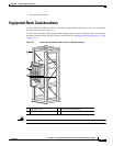
As you plan the installation of the chassis into the equipment rack, consider the following:
• Make sure that the floor mounting bolts on the equipment rack are accessible, especially if annual
retorquing of bolts is required.
• For chassis installation, you must have access to the vertical mounting rails at each corner of the
equipment rack.
• Consider whether the area around the rack is large enough to accommodate the scissor lift (or similar
lifting device) and installation personnel.
• A minimum of 48 mounting screws (provided with the chassis) are needed to secure the chassis to
the rack. To secure the chassis to the rack, you install 12 screws in each of the four corners of the
rack.
• The rack should have horizontal shelf brackets to place the chassis on. The brackets must be able to
support at least 650 lb. (294.8 kg). If the rack does not have horizontal mounting rails, a set of rails
is included in the installation kit, which is available as an option (CRS-8-INSTALL-KT=).
Caution Standard rack-mounting screws are not strong enough to secure the chassis to the equipment rack.
Use
only those mounting screws that are shipped with the chassis or those listed in the “Equipment Rack
Specifications” section on page 3-2.
For complete instructions on mounting and securing the chassis to a rack, see the Cisco CRS-1 Carrier
Routing System 8-Slot Line Card Unpacking, Moving, and Securing Guide.
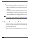
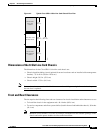
Aisle Spacing and Maintenance Access Floor Plan
The floor plan for the Cisco CRS-1 must include enough space to install the 8-slot line card chassis in
the equipment rack and allow sufficient airflow for the system. The floor plan must also provide enough
room to access chassis components for maintenance (for example, to remove fan trays, power modules,
cables, and air filters).
Figure 4-2 shows a top view of the Cisco CRS-1 8-slot line card chassis footprint required for installation
(with optional front and rear cosmetics installed).
Note For chassis installation, make sure that enough room exists in front of the chassis to accommodate
installation personnel and the scissor lift (or similar lifting device) used to hold the chassis in the rack
while it is bolted in.