


IN-1
Cisco CRS-1 Carrier Routing System 8-Slot Line Card Chassis Site Planning Guide
OL-5802-06
INDEX
Numerics
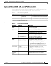
10-GE PLIM B-3
A
AC Delta PDU wiring (figure) 2-8
acoustic noise, specifications 3-6
AC power
cables 2-6
requirements 2-6
specifications 3-2
AC Wye PDU wiring (figure) 2-8
air filter 2-10
airflow
air filters check recommendation 2-10
requirements 2-11
specifications 3-6
through chassis 2-10
altitude, specifications 3-6
B
BITS clock 4-6
blanks, See impedance carriers
C
cable management bracket 4-7
cables
AC power 2-6
DC power and ground 2-3
managing 4-6
PLIM interface 4-7
power 2-6, 2-9
RP 4-7
chassis
airflow (figure) 2-10
dimensions 4-5
equipment rack installation (figure) 4-3
floor plan (figure) 4-5
front view (figure) 1-2
midplane 1-4
product IDs (table) B-1
rear view (figure) 1-3
slot numbers (figure) 1-5
specifications (table) 3-1
See also routing system
checklists, site planning A-1
clearances, chassis 4-4, 4-5
clocking, BITS 4-6
components, routing system 1-2
CONSOLE and AUX ports 4-6
cooling
requirements 2-10
specifications 3-6
D
DC earth ground cable lug (figure) 2-5
DC input power cable lug (figure) 2-4
DC PDU power cable connections (figure) 2-5
DC power
cables 2-3
requirements 2-3