


2-5
Cisco CRS-1 Carrier Routing System 8-Slot Line Card Chassis Site Planning Guide
OL-5802-06
Chapter 2 Power and Cooling
DC Power Requirements
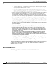
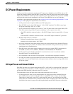
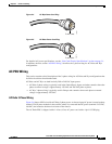
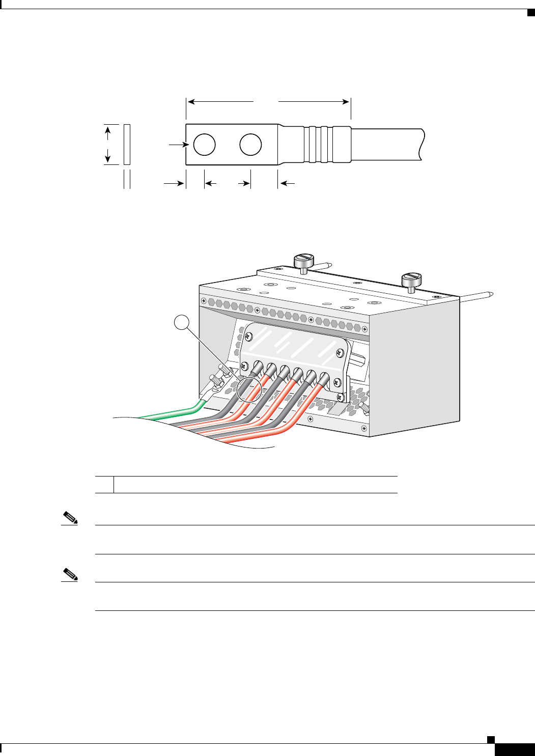
Figure 2-2 DC Earth Ground Cable Lug
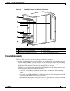
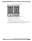
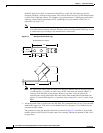
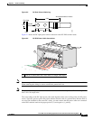
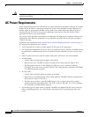
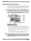
Figure 2-3 shows the DC input power cables connected to the DC PDU terminal studs.
Figure 2-3 DC PDU Power Cable Connections
Note When wiring the PDU, be sure to attach the ground wire first (shown above on the far left side of PDU).
When removing the wiring, be sure to remove the ground wire last.
Note The power wire and ground wire connector screws have a 20 in.-lb torque value. The mounting screws
have a 9 in.-lb torque value.
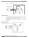
The color coding of the DC input power cable leads depends on the color coding of the site DC power
source. Typically, green or green and yellow indicates that the cable is a ground cable. Because there is
no color code standard for the source DC wiring, you must ensure that the power cables are connected
to the PDU terminal studs in the proper positive (+) and negative (–) polarity.
Crimp area
25527
2.24
0.48
0.08
0.25 0.370.63
End View
Ø 0.267
2 holes
All measurements in inches
1 Each set of cables (RTN and –48V/–60V) is a single VDC input.
129533
1