


2-4
Cisco CRS-1 Carrier Routing System 8-Slot Line Card Chassis Site Planning Guide
OL-5802-06
Chapter 2 Power and Cooling
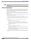
DC Power Requirements
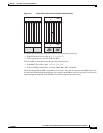
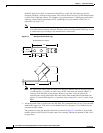
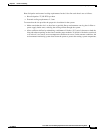
Each DC input power cable is terminated at the PDU by a cable lug. The cable lugs must be
dual-hole, and have a 45-degree angle tongue. They must be able to fit over 1/4-inch terminal studs
at 0.625-inch (15.88-mm) centers. For example, you could terminate a 2-AWG power cable with a
cable lug, such as Panduit part number LCC2-14AWH-Q (Cisco part number 32-0677-01) or
equivalent (see
Figure 2-1).
Note To avoid hazardous conditions, all components in the area where DC input power is
accessible must be properly insulated. Therefore, before installing the DC cable lugs, be sure
to insulate the lugs according to the manufacturer’s instructions.
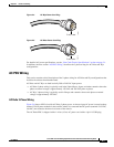
Figure 2-1 DC Input Power Cable Lug
Note DC input power cables must be connected to the PDU terminal studs in the proper positive
(+) and negative (–) polarity. In some cases, the DC cable leads are labeled, which is a
relatively safe indication of the polarity. However, you must verify the polarity by
measuring the voltage between the DC cable leads. When making the measurement, the
positive (+) lead and the negative (–) lead must always match the (+) and (–) labels on the
PDU.
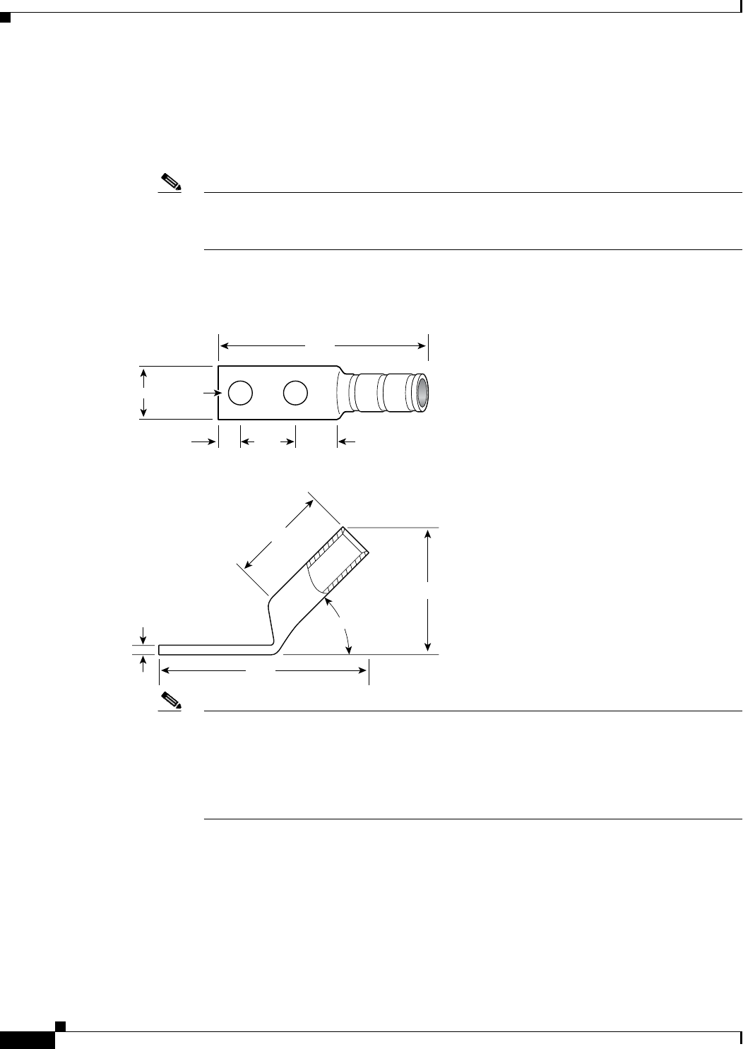
• An earth ground cable is required for each DC PDU. We recommend that you use at least 6-AWG
multistrand copper wire. This wire is not available from Cisco Systems; it is available from any
commercial cable vendor.
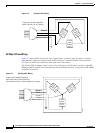
The ground wire cable lug should be dual-hole (as shown in Figure 2-2) and able to fit over M6
terminal studs at 0.625-inch (15.88-mm) centers (for example, Panduit part number LCD6-14A-L
or
equivalent).
129535
2.38
2.38
0.60
0.25 0.38
1.16
.10
1.44
45˚
0.63
Ø 0.27
2 holes
All measurements in inches