


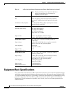
2-10
Cisco CRS-1 Carrier Routing System 8-Slot Line Card Chassis Site Planning Guide
OL-5802-06
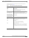
Chapter 2 Power and Cooling
Chassis Airflow
Chassis Airflow
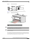
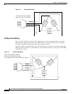
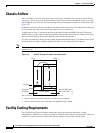
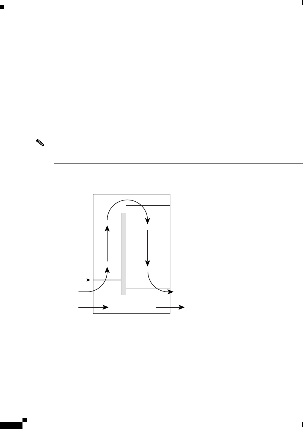
The Cisco CRS-1 8-slot line card chassis has two fan trays, with three fans each, that cool the chassis
card cages. Cool air flows in at the bottom front of the chassis and flows through the chassis card cages
and through the fans in the fan trays before being exhausted through the bottom rear of the chassis (see
Figure 2-9).
In addition, each AC or DC power module at the bottom of the chassis has self-contained fans that pull
in cool air from the front of the chassis and exhaust warm air out the rear.
A replaceable air filter is located on the front of the chassis below the PLIM card cage. Each power
module also has a replaceable air filter that attaches to the module at the front side of the chassis. How
often you should replace the air filters depends on the facility environment.
In a dirty environment or when you start getting frequent temperature alarms, you should always check
the intake grills for debris, and then check the air filters to see if they need to be replaced.
Note We recommend that you check the air filters once a month. Replace a filter when you notice a significant
amount of dust.
Figure 2-9 Airflow Through the 8-Slot Line Card Chassis
The 8-slot line card chassis airflow volumes are as follows:
• Chassis airflow: Up to 900 cubic feet (25,485 liters) per minute
• Power system airflow: Up to 240 cubic feet (6800 liters) per minute
Facility Cooling Requirements
The 8-slot line card chassis dissipates considerable power that generates much heat. In large
configurations, additional air cooling is required to maintain correct operating temperatures. The room
air must be cooled by external cooling units that are installed as part of the routing system.
122784
Fan
Air enters
PLIM side
Power system
Fan
Air exits MSC and
fabric card side
Front Rear
Air filter