


Index
IN-2
Cisco CRS-1 Carrier Routing System 8-Slot Line Card Chassis Site Planning Guide
OL-5802-06
restricted system access 2-3
safety extra-low voltage (SELV) requirements 2-3
specifications 3-2
torque value for power connector screws 2-5
dimensions, chassis 4-5
E
electrical codes 2-2
environmental specifications (table) 3-6
equipment rack
considerations 4-3
overview 4-3
specifications (table) 3-3
Ethernet ports 4-6
F
Figures
8-slot chassis in equipment rack 4-3
AC Delta PDU wiring 2-8
AC Delta power cord plug 2-7
AC Wye PDU wiring 2-8
AC Wye power cord plug 2-7
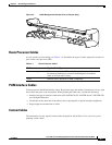
Cable Management Bracket (Front of Chassis
Only)
4-7
chassis airflow 2-10
chassis floor plan 4-5
chassis front 1-2
chassis rear 1-3
chassis slot numbers 1-5
DC earth ground cable lug 2-5
DC input power cable lug 2-4
DC PDU power cable connections 2-5
filter, air 2-10
floor plan 4-4, 4-5
G
grounding requirements 2-2, 2-9
H
heat dissipation, specifications 3-6
humidity, specifications 3-6
I
impedance carriers B-3
installation
clearance distance 4-5
installation checklist A-1
See also site planning
M
midplane, chassis 1-4
MSCs B-3
N
NEBS grounding requirements 2-9
O
OC-48/STM-16 PLIM B-3
OC-192/STM-64 PLIM B-3
OC-768/STM-256 PLIM B-3
P
PDUs
AC Delta wiring 2-7
AC Wye wiring 2-8
physical layer interface modules, See PLIMs
PLIMs
impedance carrier B-3