


6-4
Hardware Installation Guide for the Cisco 4451-X Integrated Services Router
OL-27644-01
Chapter 6 Installing and Upgrading Internal Modules and FRUs
Accessing Internal Modules
Accessing Internal Modules
To access the internal modules on the router., you must first remove the chassis cover. See the Removing
and Replacing the Chassis Cover, page 6-4 for instructions on how to remove and later replace the
chassis cover on the Cisco ISR 4451-Xs.
Removing and Replacing the Chassis Cover
The Cisco ISR 4451-Xs have a removable cover.
Caution Do not run the router with the cover off. Doing so can cause the router to overheat very quickly.
Warning
Before opening the unit, disconnect the telephone-network cables to avoid contact with
telephone-network voltages.
Statement 1041
Note Use a number-2 Phillips screwdriver to perform the following tasks.
Removing the Cover
To remove the cover, perform the following steps.
Step 1 Read the “Safety Warnings” section on page 6-2 and disconnect the power supply before you perform
any module replacement.
Step 2 Confirm the router is turned off and disconnected from the power supply or power supplies. If a
redundant power is used, disconnect from the redundant power supply.
Step 3 Place the chassis on a flat surface.
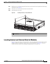
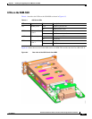
Step 4 Remove the three cover screws at the back of the router cover. See Figure 6-1.
Step 5 Lift the cover from the back edge to a 45-degree angle.
Step 6 Pull the cover toward you to disengage the slots along the front (bezel) edge of the chassis. See
Figure 6-1.
Replacing the Cover
To replace the cover, perform the following steps.
Step 1 Read the Safety Warnings, page 6-2 and disconnect the power supply before you perform any module
replacement.
Step 2 Confirm the router is turned off and disconnected from the power supply or power supplies. If a
redundant power is used disconnect from the redundant power supply.
Step 3 Place the chassis on a flat surface.