


3-11
Cisco 4400 Series Hardware Installation Guide
OL-27644-01
Chapter 3 Installing and Connecting the Router
Chassis Grounding
Chassis Grounding
Warning
This equipment must be grounded. Never defeat the ground conductor or operate the equipment in the
absence of a suitably installed ground conductor. Contact the appropriate electrical inspection
authority or an electrician if you are uncertain that suitable grounding is available.
Statement 1024
Warning
During this procedure, wear grounding wrist straps to avoid ESD damage to the card. Do not directly
touch the backplane with your hand or any metal tool, you could shock yourself.
Statement 94
You must connect the chassis to a reliable earth ground; the ground wire must be installed in accordance
with local electrical safety standards.
• For grounding, use size 6 AWG (13 mm
2
) copper wire and the ground lug provided in the accessory
kit.
Note This equipment is suitable for installation in Network Telecommunications Facilities and
locations where the NEC applies. The equipment is suitable for installation as part of the
Common Bonding Network (CBN).
• For NEC-compliant grounding, use size 14 AWG (2 mm
2
) or larger copper wire and an appropriate
user-supplied ring terminal with an inner diameter of 1/4 in. (5–7 mm).
• For EN/IEC 60950-compliant grounding, use size 18 AWG (1 mm
2
) or larger copper wire and an
appropriate user-supplied ring terminal.
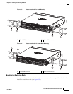
To install the ground connection for a Cisco ISR 4451-X, perform the following steps:
Step 1 Strip one end of the ground wire to the length required for the ground lug or terminal.
• For the ground lug—approximately 0.75 inch (20 mm)
• For user-provided ring terminal—as required
Step 2 Crimp the ground wire to the ground lug or ring terminal, using a crimp tool of the appropriate size.
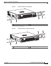
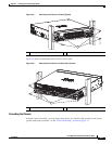
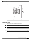
Step 3 Attach the ground lug or ring terminal to the chassis as shown in Figure 3-7. For a ground lug, use the
two screws with captive locking washers provided. For a ring terminal, use one of the screws provided.
Tighten the screws to a torque of 8 to 10 in-lb (0.9 to 1.1 N-m).