


1-11
Hardware Installation Guide for the Cisco 4451-X Integrated Services Router
OL-27644-01
Chapter 1 Overview of the Cisco 4451-X Integrated Services Router
Hardware Features
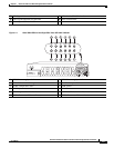
Internal PoE card
The internal PoE daughter card provides a total of 30.8 Watts of power across the 2 ports.
LED Indicators
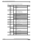
Table 1-1 summarizes the LED indicators that are located in the router bezel or chassis, but not on the
interface cards and modules.
Note For module LEDs, please refer to the respective module installation guides for each module.
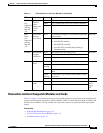
Table 1-1 LED Indicators on the Cisco ISR 4451-X
LED Represents Color Description Location
STAT System
Status
Solid
green
Normal System Operation. Bezel side
Blinking
amber
BIOS/Rommon is in the process of booting.
Amber BIOS/Rommon has completed booting and system
at Rommon prompt or booting platform software.
Off System is not out of reset or BIOS image not
loadable.
TEMP Temperature
Status
Solid
green
All temperature sensors in the system are within
acceptable range.
Bezel side
Amber One or more temperature sensors in the system are
outside the acceptable range.
Off Temperature is not being monitored.
FAN Fan Status Green All fans are operating. Bezel side
Amber One fan has stopped working.
Blinking
Amber
Two or more fans have stopped working, or the fan
tray has been removed.
Off Fans are not being monitored.
L
(left)
Ethernet
ports 0 and 1
Link
Green Ethernet cable present and link established with
other side or PoE power is enabled for this port.
I/O side
Amber Yellow: PoE power for this connector is faulty and
link is down. (Only for Ethernet port 0 and 1.)
Off No link.
S
(left)
Speed of
Ethernet
ports 0 and 1
Green
Blinking
Blink frequency indicates port speed:
1 blink - 10Mbps link speed
2 blinks - 100Mbps link speed
3 blinks - 1000Mbps link speed
I/O side
Off No link or a non-Ethernet 802.3af/t capable device
plugged in and powered over the PoE.