


1-20
Hardware Installation Guide for the Cisco 4451-X Integrated Services Router
OL-27644-01
Chapter 1 Overview of the Cisco 4451-X Integrated Services Router
Specifications
About Slot 1 and 2
Slot 1 and slot 2 are NIM slots. All enhanced SM slots start with 1.
Additional Slots
The Cisco ISR 4451-Xs have the following additional slots:
• P0: Field upgradable power supply slot 0
• P1: Field upgradable/replaceable power supply slot 1.
• INT-POE: Internal PoE card slot.
Subslot/Bay Numbering
• Integrated devices, also known as integrated ports or FPGEs, and integrated NIMs reside in a fixed
section of bay 0.
• Main board NIMs bays start at bay 1, since the integrated devices and integrated NIMs take up bay 0.
• The bay numbers for PVDM4s start with the next bay number after the last NIM bay number.
• The two modular SATA slots share the same bay as the third NIM slot.
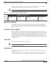
Gigabit Ethernet Management
The Cisco ISR 4451-X provides a Gigabit Ethernet Management port, called GE0. This port is the only
1-tuple port on the system. See the <chapter on Ethernet Management in SW Configuration Guide> for
additional information about the Gigabit Ethernet Management port.
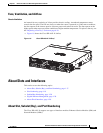
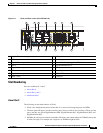
About Fixed Interfaces
The router supports fixed interfaces on the motherboard and on service modules. The system treats the
onboard interfaces as if they lived on a virtual NIM plugged into bay 0. In this case, the front panel
GigabitEthernet ports are considered slot 0 bay 0 (0/0/x). The onboard ports on the service module are
slot 1 bay 0 (1/0/x).
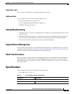
Specifications
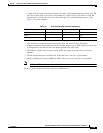
The following tables provide Cisco ISR 4451-X specifications.
• Cisco ISR 4451-X—Table 1-5
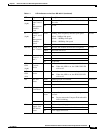
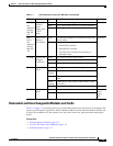
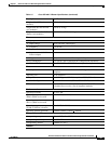
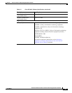
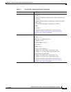
Table 1-5 Cisco ISR 4451-X Router Specifications
Description Specification
Physical
Dimensions (H x W x D) 3.5 x 17.25 x 18.7 in. (88.9 x 438.2 x 474.9 mm), 2 RU height