


6-27
Hardware Installation Guide for the Cisco 4451-X Integrated Services Router
OL-27644-01
Chapter 6 Installing and Upgrading Internal Modules and FRUs
Installing and Removing the PVDM4
Installing the PVDM4 on the Motherboard of the Cisco ISR 4451-X
Step 1 Read the “Safety Warnings” section on page 6-2 and disconnect the power supply before you perform
any module replacement.
Step 2 Turn off electrical power to the router. Leave the power cable plugged in to channel ESD voltages to
ground.
Step 3 Remove the cover.
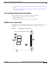
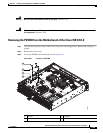
Step 4 Identify the ISC slot on the router’s main motherboard.
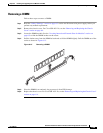
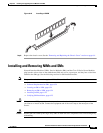
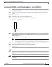
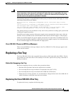
Step 5 Locate the three standoffs from the accessory kit. See Figure 6-20.
Figure 6-20 Standoffs
Step 6 Install the three standoffs into the system board in the attachment locations. Use a 1/4-inch nut driver to
tighten the standoffs. The locations for PVDM4 standoffs have white plastic grommets surrounding the
mounting hole location.
Step 7 Insert the PVDM4 into the ISC slot on the system board.
Note Be sure to press firmly on the PVDM4 until the board seats onto the connector.
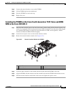
Step 8 Insert the screws from the accessory kit through the PVDM4 into the standoffs. Carefully tighten the
screws with a Phillips screwdriver (torque 6 to 8 in-lb. or 0.7 to 1.1 Nm).
Step 9 Check that the PVDM4 is installed correctly on the system board.
Step 10 Replace the cover.
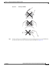
Caution When you remove or install the PVDM4, always wear an ESD-preventive wrist strap, and ensure that it
makes good contact with your skin. Connect the equipment end of the wrist strap to the metal part of the
chassis.
Caution Handle the PVDM4 by the edges only. PVDM4s are ESD-sensitive components and can be damaged by
mishandling.
121202