


1-5
Hardware Installation Guide for the Cisco 4451-X Integrated Services Router
OL-27644-01
Chapter 1 Overview of the Cisco 4451-X Integrated Services Router
Chassis Views
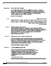
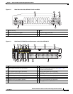
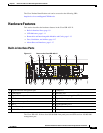
Figure 1-2 Bezel side of the Cisco ISR 4451-X with two PSUs
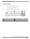
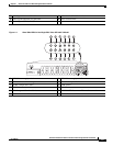
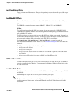
Figure 1-3 Back Panel (I/O Side) Slots and Connectors on the Cisco ISR 4451-X
1 Router fan tray 2 LEDs
3 Router power On/Off switch 4 AC power supply unit (P1)
5 AC power supply unit (P0)
Cisco 4400 Series
285695
PSU1 PSU2
POE1 POE2
FLASH TEMP PWR
VM FAN STAT
INT
POE
BOOST
1 2 3
45
1 GE 0 management port 2 Auxiliary port
3 RJ45 Gigabit Ethernet port (GE 0/0/0) 4 LEDs for the GE 0/0/0 interface (See Table 1-1 for
detailed LED information)
5 SFP Gigabit Ethernet port (GE 0/0/0) 6 SFP Gigabit Ethernet port (GE 0/0/2)
7 LEDs for the GE 0/0/2 interface 8 RJ45 Gigabit Ethernet port (GE 0/0/2)
9 NIM slot 1 10 NIM slot 2
11 NIM slot 3 (Optional Modular SSD Slot) 12 Enhanced Service Module (SM-X) 2
13 Enhanced Service Module (SM-X) 1 14 RJ45 Gigabit Ethernet port GE 0/0/3
15 LEDs for the GE 0/0/3 interface 16 SFP Gigabit Ethernet GE 0/0/3
2
1
285698
1 2 3 5 6 8 9 10 11
4 7
12
13
182123 15
17 16 14
20 1922