


6-36
Hardware Installation Guide for the Cisco 4451-X Integrated Services Router
OL-27644-01
Chapter 6 Installing and Upgrading Internal Modules and FRUs
Removing and Installing a CompactFlash Memory Card
Removing and Installing a CompactFlash Memory Card
This section describes installing and replacing CompactFlash (CF) memory cards in Cisco ISR 4451-Xs.
It contains the following sections:
• Preventing Electrostatic Discharge Damage, page 6-36
• Removing a CompactFlash Memory Card, page 6-36
• Installing a CompactFlash Memory Card, page 6-37
Note You must turn off the power supply to the router to replace a CompactFlash Memory card. A
CompactFlash memory card must be inserted in order to run a Cisco IOS XE software image.
Preventing Electrostatic Discharge Damage
CF memory cards are sensitive to electrostatic discharge (ESD) damage, which can occur when
electronic cards or components are handled improperly. ESD results in complete or intermittent failures.
To prevent ESD damage, follow these guidelines:
• Always use an ESD wrist or ankle strap and ensure that it makes good skin contact.
• Connect the equipment end of the strap to an unfinished chassis surface.
• Place CF memory cards on an antistatic surface or in a static shielding bag. If the card will be
returned to the factory, immediately place it in a static shielding bag.
• Avoid contact between the card and clothing. The wrist strap protects the card from ESD voltages
on the body only; ESD voltages on clothing can still cause damage.
• Do not remove the wrist strap until the installation is complete.
Caution For safety, periodically check the resistance value of the antistatic strap. The measurement should be
between 1 and 10 megohms (Mohms).
Removing a CompactFlash Memory Card
To remove a CF memory card from the chassis, perform the following steps:
Caution Do not remove a CF memory card from the chassis while it is being accessed. Cisco recommends not
removing the CF when in Cisco IOS-XE at all. Either power the system off or fall back to the rommon
prompt, if removing the CF. .
Step 1 Read the “Safety Warnings” section on page 6-2 section and disconnect the power supply before you
perform any module replacement.
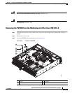
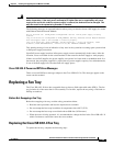
Step 2 Remove the fan tray. For instructions on removing the fan tray, see “Replacing the Cisco ISR 4451-X
Fan Tray” section on page 6-34.
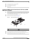
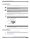
Step 3 Remove the CF cover by placing a flat-blade screwdriver in the slot and pushing sideways against the
tensioner to release the cover door.