


6-5
Hardware Installation Guide for the Cisco 4451-X Integrated Services Router
OL-27644-01
Chapter 6 Installing and Upgrading Internal Modules and FRUs
Locating Internal and External Slots for Modules
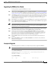
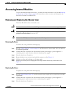
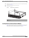
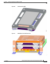
Step 4 Hold the cover at a 45-degree angle and insert the cover tabs into the slots along the front (bezel) edge
of the chassis. See Figure 6-1.
Step 5 Center the cover over the chassis and lower it onto the chassis.
Step 6 Install the three cover screws.
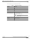
Figure 6-1 Installing the Cover on Cisco ISR 4451-Xs
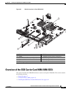
Locating Internal and External Slots for Modules
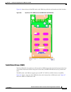
Figure 6-2 shows the locations of internal modules on the router motherboard. Internal modules include
DIMMs, PVDM4, Voice Modules, and PoE cards on the Cisco ISR 4451-X. Figure 6-21 shows the
location of the the available slots including the Integrated Services Card (ISC) slot.
1 Cover screws (3)
303010
1