


6-29
Hardware Installation Guide for the Cisco 4451-X Integrated Services Router
OL-27644-01
Chapter 6 Installing and Upgrading Internal Modules and FRUs
Installing and Removing the PVDM4
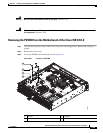
Step 4 Loosen and remove the three screws on the PVDM4.
Step 5 Lift the PVDM4 up from the motherboard.
Step 6 Place the PVDM4 in an anti-static bag.
Step 7 Replace the cover.
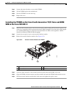
Installing the PVDM4 on the Cisco Fourth-Generation T1/E1 Voice and WAN
NIM in the Cisco ISR 4451-X
Step 1 Shut down the electrical power to the slot in the router by either turning off the electrical power to the
router or by issuing the online insertion and removal (OIR) commands. Leave the power cable plugged
in to channel ESD voltages to ground. For more information on OIR, see the Appendix, “Online
Insertion and Removal (OIR) and Hot-Swapping”.
Step 2 Loosen the two captive screws on the network interface module.
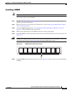
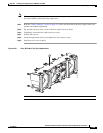
Step 3 Remove the network interface module. (See Figure 6-22.)
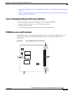
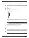
Figure 6-22 Network Interface Module with PVDM4
Step 4
Locate the three standoffs on the network interface module where the PVDM4 will reside.
Step 5 Align the PVDM4 with the connector and the standoffs and attach the PVDM4 with the three screws.
Step 6 Slide the network interface module back in the router and tighten the captive screws.
345528
2
3
1
4
1
1 Captive Screws 2 Ports
3 Network Card 4 PVDM4