


6-33
Hardware Installation Guide for the Cisco 4451-X Integrated Services Router
OL-27644-01
Chapter 6 Installing and Upgrading Internal Modules and FRUs
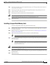
Replacing Power Supplies and Redundant Power Supplies
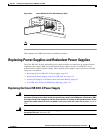
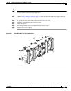
Replacing the Power Supply on the Cisco ISR 4451-Xs
Caution Care should be taken while removing the power supplies and power inverter, especially in boost mode
of operation. If the total power consumption is higher than can be supported by one PSU alone, and in
this condition, if a PSU is removed, the hardware can be damaged. This may result in the system being
unstable or unusable.
Similarly if there is only one PoE converter and it is providing PoE power to an SM, in this condition if
the PoE inverter is removed, the hardware may be damage and may result in the system being unstable
or unusable.
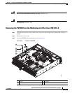
Step 1 Read the “Safety Warnings” section on page 6-2 section and disconnect the power supply before you
perform any module replacement.
Step 2 Pull on the quick-release catch on the side to leverage the power supply from its connector, and then slide
the power supply module out of the chassis.
Step 3 Insert the replacement power supply module.
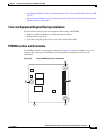
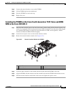
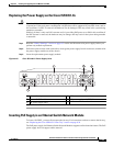
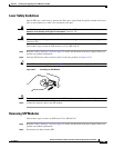
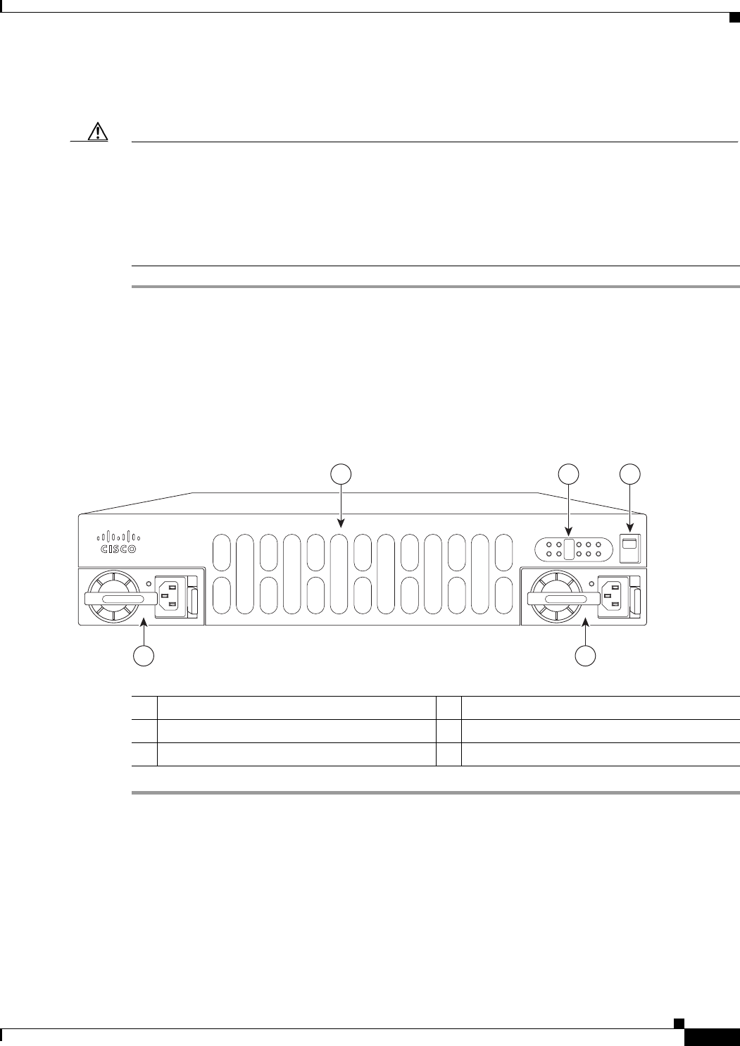
Figure 6-25 Cisco ISR 4451-X Power Supply Units
.
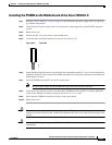
Inserting PoE Supply in an Ethernet Switch Network Module
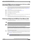
To insert a PoE PSU, you must first remove the fan tray. For instructions on how to remove the fan tray,
see “Replacing the Cisco ISR 4451-X Fan Tray” section on page 6-34
The PoE power supply for Ethernet Switch Network Modules supports online insertion feature. The PoE
power supply does not support online removal.
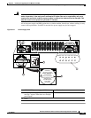
1 Router fan tray 2 LEDs
3 Router On/Off switch 4 AC power supply unit (PSU) 2
5 AC power supply unit 1
Cisco 4400 Series
285695
PSU1 PSU2
POE1 POE2
FLASH TEMP PWR
VM FAN STAT
INT
POE
BOOST
1 2 3
45