


1-2
Hardware Installation Guide for the Cisco 4451-X Integrated Services Router
OL-27644-01
Chapter 1 Overview of the Cisco 4451-X Integrated Services Router
Safety Warnings
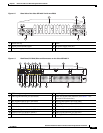
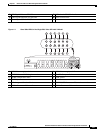
• 1 RJ45 Console
• 1 RJ45 AUX port with full modem control signals
• 4 10/100/1000 RJ-45 Ethernet ports (labeled GE 0/0/0, 0/0/1, 0/0/2, and 0/0/3)
• 4 100/1000 SFP Ethernet ports (labeled SFP 0/0/0, 0/0/1, 0/0/2, and 0/0/3)
• LEDs for Ethernet and console status
• LEDs for SATA hard disk drive activity and status (available on certain models)
• Two DDR3 240 pin Control Plane DIMM slots which can be replaced
• One DDR3 240 pin Data Plane DIMM slot which can be replaced
• One compact flash slot, which is serviceable when the fan tray is removed
• One 30W PoE daughter card for two of the front Gigabit Ethernet ports which can be replaced
(labeled GE 0/0/0 and 0/0/1)
• One Packet Voice Digital Signal Processor Module (PVDM4) providing IP Voice and video
capability
• Environment monitoring
• Field replaceable fan tray
• Dual redundant power supply units (PSUs) and PoE PSU.
This chapter contains the following sections:
• Safety Warnings, page 1-2
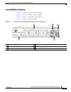
• Chassis Views, page 1-3
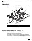
• Locating the Serial Number, PID, VID and CLEI, page 1-7
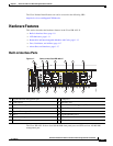
• Hardware Features, page 1-9
• About Slots and Interfaces, page 1-17
• Specifications, page 1-20
• Periodic Inspection and Cleaning, page 1-25
Safety Warnings
Warning
IMPORTANT SAFETY INSTRUCTIONS
This warning symbol means danger. You are in a situation that could cause bodily injury. Before you
work on any equipment, be aware of the hazards involved with electrical circuitry and be familiar
with standard practices for preventing accidents. Use the statement number provided at the end of
each warning to locate its translation in the translated safety warnings that accompanied this device.
Statement 1071
SAVE THESE INSTRUCTIONS