


1-18
Hardware Installation Guide for the Cisco 4451-X Integrated Services Router
OL-27644-01
Chapter 1 Overview of the Cisco 4451-X Integrated Services Router
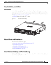
About Slots and Interfaces
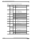
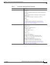
• In most cases, the router designates its interfaces using a 3-tuple notation that lists the slot, bay, and
port. The 3-tuple value is zero based. An example of a 3-tuple is 0/1/2. This refers to slot 0, the
second bay in slot 0 (the first bay is 0 so the second bay is 1), and the third port in bay 1. See
Table 1-4 for more examples.
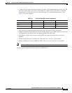
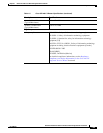
Table 1-4 Slot, Subslot (Bay) and Port Numbering
• Slots and bays are numbered from the left to the right, and from the top to the bottom.
• NIMs are designated by the number of the first slot that they occupy. A NIM occupies two slots, but
its designation is only the left-most slot number (double-wide cards only).
• The auxiliary (AUX) serial port and console (CON) serial port do not have slot, bay, or port
numbers.
• The GE management port is named GE 0. It does not have a slot, bay, or port number.
• The two USB ports are named USB0 and USB1. They do not have slot, bay or port numbers
Note USB0 and USB1 can be used to insert flash drives..
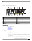
Figure 1-9 shows the ports and slots on the Cisco ISR 4451-Xs.
3-Tuple Example Slot Bay Port
0/1/2 0 2nd 3rd
0/0/1 0 1st 2nd
1/1/1 1 2nd 2nd