


8 - 7
SETTING SYSTEM PARAMETERS
ETC00781(4) Series 100 e 02/2004
ANALOG SIGNAL OUTPUTS
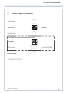
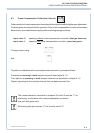
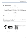
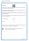
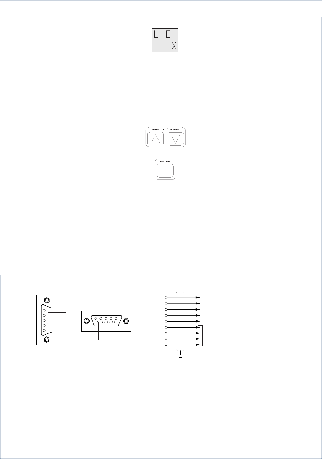
Fig. 8-1: Pin assignments mating socket X 2 (analog signal outputs)
1
⊥⊥
⊥⊥
⊥ (V DC)
2 0 (2) - 10 V DC [Option: 0 (0,2) - 1 V DC], channel 1
3 0 (4) - 20 mA, channel 1 (R
B
≤ 500 Ω)
4 0 (2) - 10 V DC [Option: 0 (0,2) - 1 V DC], channel 2
5 0 (4) - 20 mA, channel 2 (R
B
≤ 500 Ω)
6
7
8
9
⊥⊥
⊥⊥
⊥ (mA)
8.8 Analog Signal Outputs
The analog signal outputs (optically isolated) are brought out to a 9 pin sub miniature D
connector X2 on the analyzer rear panel. Refer to the wiring hints in chapter 29.10 !
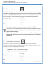
Input value 0: Output signal is 0 - 10 Vdc (Option: 0 - 1 Vdc) / 0 - 20 mA.
Input value 1: Output signal is 2 - 10 Vdc (Option: 0.2 - 1 Vdc) / 4 - 20 mA (life zero mode)
Change values using
and
Note:
The begin of range concentration (OFS.) and the end of range concentration (END) are freely
programmable (see chapter 8.12 and 8.13).
For type of voltage output (standard or option)please refer to order confirmation or identification
label.
6
9
1
5
6
9
15