


CHECKING AND REPLACING AN ELECTROCHEMICAL OXYGEN SENSOR
25 - 7
ETC00781(4) Series 100 e 02/2004
BASIC SETTINGS
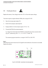
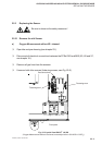
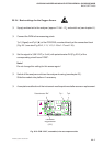
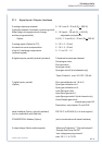
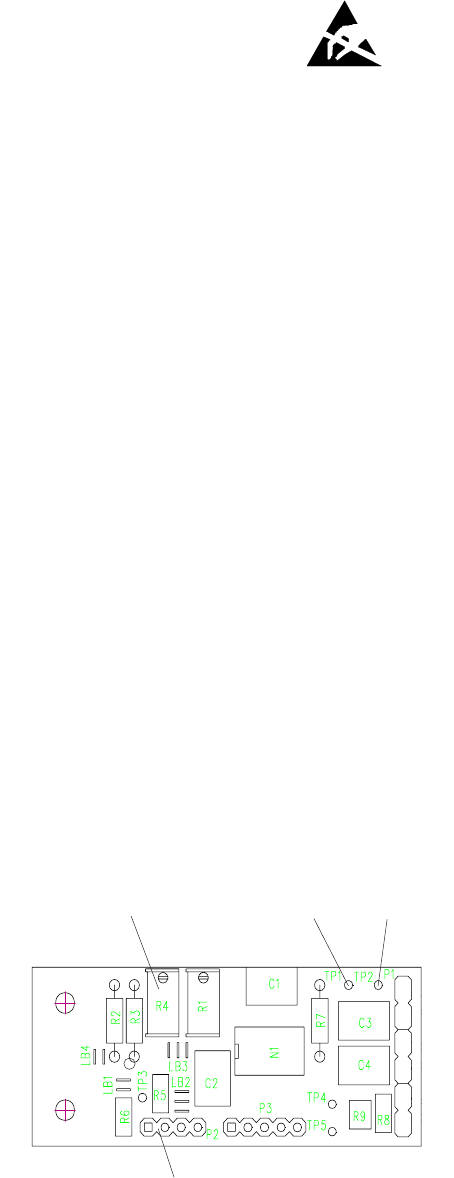
Fig. 25-5: PCB “OXS”, assembled, view at component side
25.2.4 Basic settings for the Oxygen Sensor
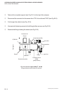
P Supply ambient air to the analyzer (approx. 21 Vol. - O
2
) and switch on (see chapter 6.).
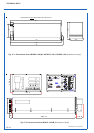
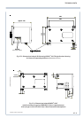
P Connect the DVM to the measuring points
Tp 1 (Signal) and Tp 2 (
⊥⊥
⊥⊥
⊥ ) of the PCB OXS, mounted directly at the connection block
(Fig. 25-1, see also Fig. 25-2, 1-11, 1-13, 1-15 to 1-17 and 1-19).
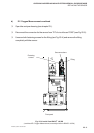
P Set the signal to 3,36 V DC (± 5 mV) with potentiometer R4 (Fig. 25-5) of the
corresponding circuit board “OXS”.
Note !
Do not change this setting for this sensor again !
P Switch off the analyzer and close the analyzer housing (see chapter 23.).
Slide the module into platform if necessary.
P A complete recalibration of the instrument must be performed after a sensor replacement.
Connection
oxygen sensor
(“P2”)
Tp 1 Tp 2
Potentiometer “R4”